Kia Optima DL3: Rear Suspension System / Trailing Arm
Repair procedures
| Removal |
| 1. |
Disconnect the (-) battery terminal. |
| 2. |
Remove the rear wheel and tire. (Refer to Tires/Wheels - "Wheel") |
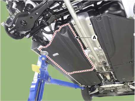
| 3. |
Remove the under cover (A).
|
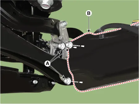
| 4. |
Loosen the nut (A) and remove trailing arm (B) from rear axle.
|
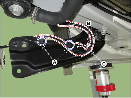
| 5. |
Loosen the fastener (A) and the bracket mounting bolt (B) and remove the rear wheel speed sensor line (C) from the trailing arm.
|
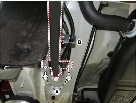
| 6. |
Loosen the mounting bolt (A) and remove the trailing arm (B).
|
| Inspection |
| 1. |
Check the bushing for wear and deterioration. |
| 2. |
Check the trailing arm for deformation. |
| 3. |
Check for all bolts and nuts. |
| Installation |
| 1. |
Install in the reverse order of removal. |
| 2. |
Check the alignment. (Refer to Suspension System - "Alingment") |
Repair procedures Removal 1. Disconnect the (-) battery terminal. 2. Remove the rear wheel and tire.
Repair procedures Removal 1. Disconnect the (-) battery terminal. 2. Loosen the bolt and nut (A) and then disconnect the rear stabilizer link from the rear lower arm.
Other information:
Kia Optima DL3 2019-2026 Service and Repair Manual: Cluster Ionizer
Components and components location Components Location 1. Condenser Description and operation Description The cluster ionizer makes disinfection and decomposition of bad smell from the air-conditioner or inflow air.
Kia Optima DL3 2019-2026 Service and Repair Manual: Power Mosfet
Description and operation Description It is installed to the DATC and adjusts the fan rpm by precisely controlling the voltage applied to the blower motor. Repair procedures Inspection 1. Turn the ignition switch ON.
Categories
- Manuals Home
- Kia Optima Owners Manual
- Kia Optima Service Manual
- Engine Mechanical System
- Engine Control / Fuel System
- Headlamps
- New on site
- Most important about car
