Kia Optima DL3: Cylinder Block / Piston and Connecting Rod
Components and components location
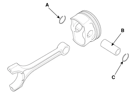
| Components |
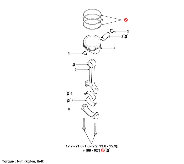
| 1. Piston ring 2. Snap ring 3. Piston pin 4. Piston |
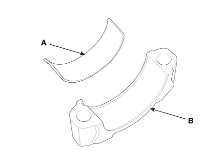
5. Connecting rod 6. Connecting rod upper bearing 7. Connecting rod lower bearing 8. Connecting rod bearing cap |
Repair procedures
| Disassembly |
Engine removal is required for this procedure.
|

|

| 1. |
Remove the engine assembly from the vehicle. (Refer to Engine and Transaxle Assembly - “Engine and Transaxle Assembly”) |
| 2. |
Remove the transaxle assembly from the engine assembly. (Refer to Automatic Transaxle System - "Automatic Transaxle") |
| 3. |
Remove the drive plate. (Refer to Cylinder Block - "Drive Plate") |
| 4. |
Remove the rear oil seal. (Refer to Cylinder Block - “Rear Oil Seal”) |
| 5. |
Install the engine to engine stand for disassembly. |
| 6. |
Remove the timing chain. (Refer to Timing System - “Timing Chain”) |
| 7. |
Remove the water pump assembly. (Refer to Cooling System - “Water Pump”) |
| 8. |
Remove the water inlet fitting and the thermostat assembly. (Refer to Cooling System - “Thermostat“) |
| 9. |
Remove the intake manifold. (Refer to Intake and Exhaust System - "Intake Manifold") |
| 10. |
Remove the A/C compressor. (Refer to Heating, Ventilation Air conditioning -"Compressor") |
| 11. |
Remove the exhaust manifold. (Refer to Intake and Exhaust System - "Exhaust Manifold") |
| 12. |
Remove the cylinder head assembly. (Refer to Cylinder Head Assembly - "Cylinder Head") |
| 13. |
Remove the oil filter. (Refer to Lubrication System - “Engine Oil”) |
| 14. |
Remove the oil screen. (Refer to Lubrication System - “Oil Pan”) |
| 15. |
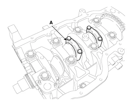
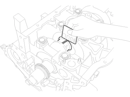
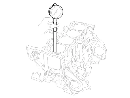
Check the connecting rod side clearance. |
| 16. |
Check the connecting rod bearing cap oil clearance. |
| 17. |
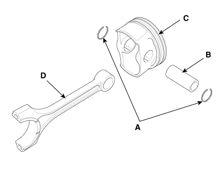
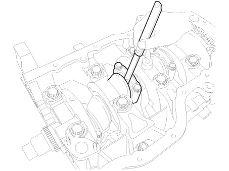
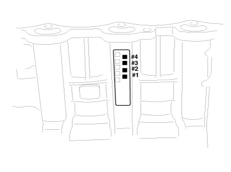
Remove the piston and connecting rod assemblies.
|
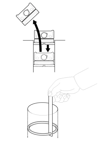
| 18. |
Check fit between piston and piston pin. Try to move the piston back and forth on the piston pin. If any movement is felt, replace the piston and pin as a set. |
| 19. |
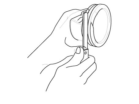
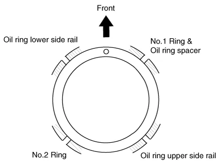
Remove piston rings.
|
| 20. |
Disassemble the connecting rod from the piston.
|
| Inspection |
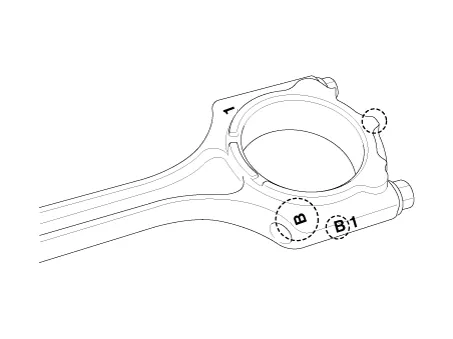
Connecting Rod
| 1. |
Check the connecting rod side clearance. Using a feeler gauge, measure the end play while moving the connecting rod back and forth.
|
| 2. |
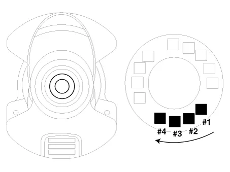
Check the connecting road bearing oil clearance.
|
|||||||||||||||||||||||||||||||||||||||||||||||||||||||||||||||||||||||||||||||||||||||||||||||||||||||||||||||
| 3. |
Check the connecting rods.
|
Piston
| 1. |
Clean piston.
|
| 2. |
Check the piston-to-cylinder clearance by calculating the difference between the cylinder bore inner diameter and the piston outer diameter.
|
| 3. |
Select the piston matching with cylinder bore class.
|
Piston Rings
| 1. |
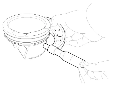
Inspect the piston ring side clearance. Using a feeler gauge, measure the clearance between new piston ring and the wall of ring groove. If the clearance is greater than maximum, replace the piston.
If the clearance is greater than maximum, replace the piston. |
| 2. |
Inspect piston ring end gap. To measure the piston ring end gap, insert a piston ring into the cylinder bore. Position the ring at right angles to the cylinder wall by gently pressing it down with a piston. Measure the gap with a feeler gauge.
If the gap exceeds the service limit, replace the piston rings. If the gap is too large, recheck the cylinder bore inner diameter. If the bore is over the service limit, the cylinder block must be replaced. |
Piston Pins
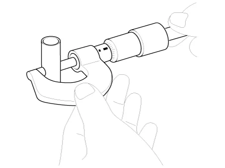
| 1. |
Measure the diameter of the piston pin.
|
| 2. |
Measure the piston pin-to-piston clearance.
|
| 3. |
Check the clearance between the piston pin outer diameter and the connecting rod small end inner diameter.
|
| Reassembly |
|
| 1. |
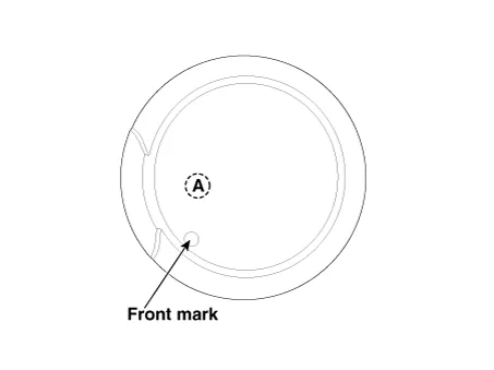
Assemble the piston and the connecting rod.
|
| 2. |
Install the piston rings.
|
| 3. |
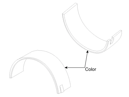
Install the connecting rod bearings.
|
| 4. |
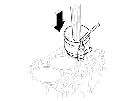
Install the piston and connecting rod assemblies.
|

| 5. |
Check the connecting rod end play. |
| 6. |
Assemble the other parts in the reverse order of disassembly. |
Components and components location Components 1. Rear Oil Seal Repair procedures Replacement 1.
Components and components location Components 1. Crankshaft upper bearing 2. Crankshaft thrust bearing 3. Crankshaft 4.
Other information:
Kia Optima DL3 2019-2026 Service and Repair Manual: Hazard Lamp Switch
Schematic diagrams Connector and Terminal Function Repair procedures Removal 1. Disconnect the negative battery terminal. 2. Remove the crash pad garnish [RH]. (Refer to Body - "Crash Pad Garnish") 3.
Kia Optima DL3 2019-2026 Service and Repair Manual: Rheostat
Schematic diagrams Connector and Terminal Function Repair procedures Removal 1. Disconnect the negative battery terminal. 2. Remove the crash pad lower panel. (Refer to Body - "Crash Pad Lower Panel") 3.
Categories
- Manuals Home
- Kia Optima Owners Manual
- Kia Optima Service Manual
- Front Axle Assembly
- Battery
- Cooling System
- New on site
- Most important about car
