
Kia Optima DL3: Cylinder Block / Drive plate
Components and components location
| Components |
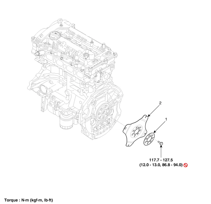
| 1. Adapter plate |
2. Drive plate |
Repair procedures
| Removal and Installation |
| 1. |
Remove the automatic transaxle. (Refer to Automatic Transaxle System - "Automatic Transaxle") |
| 2. |
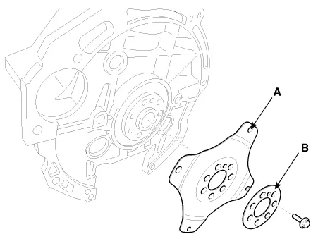
Remove the drive plate (A) and the adapter plate (B).
|

| 3. |
Install in the reverse order of removal. |
Components and components location Components 1. Piston ring 2. Snap ring 3. Piston pin 4.
Components and components location Components 1. Rear Oil Seal Repair procedures Replacement 1.
Other information:
Kia Optima DL3 2019-2026 Service and Repair Manual: Integrated Memory Seat (IMS) Switch
Schematic diagrams Connector and Terminal Function Repair procedures Removal When prying with a flat-tip screwdriver or use a prying trim tool, wrap it with protective tape, and apply protective tape around the related parts, to prevent dam
Kia Optima DL3 2019-2026 Service and Repair Manual: Cluster Ionizer
Components and components location Components Location 1. Condenser Description and operation Description The cluster ionizer makes disinfection and decomposition of bad smell from the air-conditioner or inflow air.
Categories
- Manuals Home
- Kia Optima Owners Manual
- Kia Optima Service Manual
- Floor Console Assembly
- CVVT Oil Control Valve (OCV)
- Headlamps
- New on site
- Most important about car
