
Kia Optima DL3: Body Side Molding / Side Sill Molding
Repair procedures
| Replacement |
Put on gloves to prevent hand injuries. |

|

| 1. |
Remove the front wheel guard. (Refer to Body Side Molding - "Front Wheel Guard") |
| 2. |
Remove the rear wheel guard. (Refer to Body Side Molding - "Rear Wheel Guard") |
| 3. |
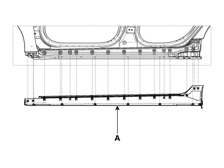
Using a remover and remove the side sill molding (A).
|
| 4. |
To install, reverse the removal procedure.
|

Repair procedures Replacement • Put on gloves to prevent hand injuries.
Repair procedures Replacement Put on gloves to protect your hands. • Use a plastic panel removal tool to remove interior trim pieces without marring the surface.
Other information:
Kia Optima DL3 2019-2026 Service and Repair Manual: Panorama Sunroof Motor
Schematic diagrams Connector and Terminal Function Repair procedures Inspection 1. Disconnect the negative battery terminal. 2. Remove the rear pillar trim [LH]. (Refer to Body - "Rear Pillar Trim") 3.
Kia Optima DL3 2019-2026 Service and Repair Manual: Heater Control Unit
Components and components location Components Connector Pin Function [Connector A] Pin NO Funtion Pin NO Funtion 1 Ground 11 Ground 2 Clean signal 12 -
Categories
- Manuals Home
- Kia Optima Owners Manual
- Kia Optima Service Manual
- Floor Console Assembly
- Timing Chain
- Automatic Transaxle System
- New on site
- Most important about car
