Kia Optima DL3: Advanced Driver Assistance System (ADAS) / Surround View Monitor (SVM)
Components and components location
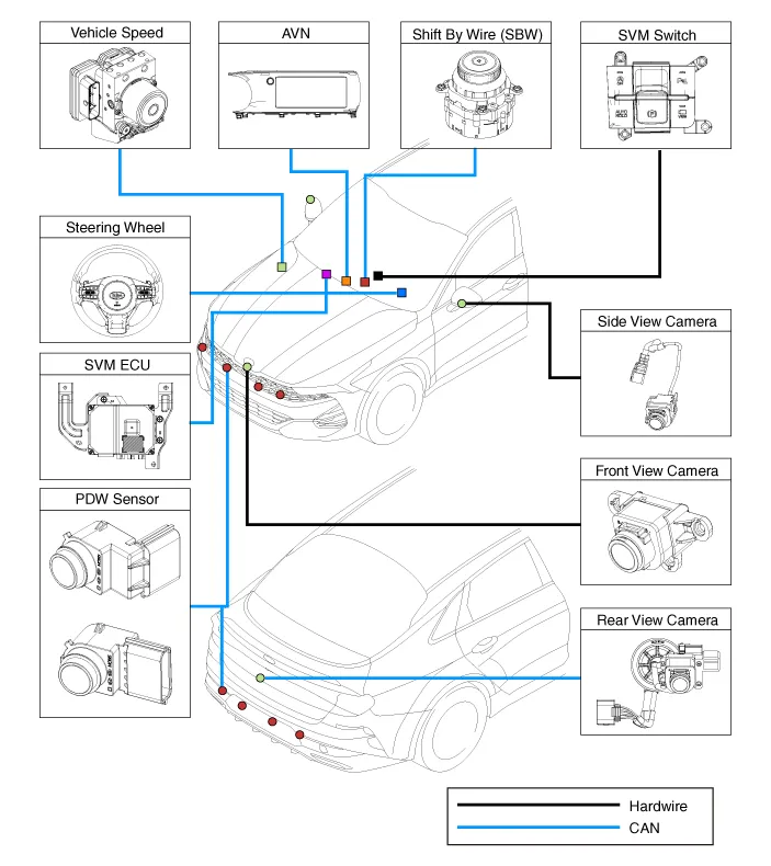
| Component Location |
| Surround View Monitor (SVM) |
|

| Component Functions |
| – |
Steering Wheel Sensor : The steering wheel angle is transmitted to the SVM unit through the C-CAN communication line for display of the rear view and steering assisted parking guideline. |
| – |
Transmission : The shift lever position is transmitted to the SVM to determine its operation. |
| – |
Front/Rear PDW : An alarm screen to display obstacles appears on the omnidirectional monitor that receives data from the parking distance warning (PDW) sensor on the front and rear. |
| – |
SVM Unit : It controls the overall operations for video signal processing/input/output, vehicle communication (CAN), and SVM system. |
| – |
SVM Switch : The SVM switch signals are input to determine whether or not to provide images in forward display mode. |
| – |
Vehicle Speed Sensor : The vehicle speed is transmitted to the SVM to check the SVM operation condition. |
| – |
Camera (4 unit) : Each unit is mounted on the front, rear, and left/right outside mirrors to capture images from the surroundings and to transmit them to the SVM unit. |
| – |
AVN Monitor : It provides the driver with the output image from the SVM unit through the monitor of the AVN (Audio, Video and Navigation system) head unit. |
Description and operation
| Description |
Surround View Monitor (SVM) allows video monitoring of 360 degrees around the vehicle. The system consists of 4 ultra optical cameras mounted around the vehicle (front, both sides and rear).
The video images from these cameras are applied with distortion compensation, time point conversion, and video merging technologies to provide sky-view image of the vehicle's surrounding area, as well as various other view modes.
The SVM System provides video feed of the vehicle's surrounding area while parking or during low speed driving to the driver to enhance safety and driver's convenience.
Also, it features steering wheel synchronized guide line indication, front and rear object warning, and A/S (including In-Line) tolerance compensation.
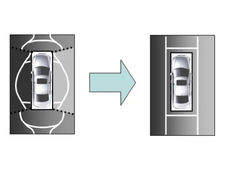
This system displays the video images from ultra optical cameras mounted on 4 sides of the vehicle, on the Head Unit Screen. It shows 360 degrees sky-view image of the vehicle's arounding area, as well as various other view modes.
Blind-spot View Monitor (BVM)
Blind-spot View Monitor (BVM) is a driving safety system that helps provide a more comprehensive views on areas which is not usually visible by the side mirrors when the vehicle tries to change the lane.
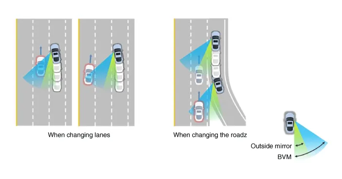
The BVM system provides a driver a more comprehensive view which is not usually visible by the side mirrors in certain situations like swithing drive lanes. The system helps to avoid any blind spot mishaps.
| – |
The rear side view is displayed in the cluster screen when the turning lights are in operation as the light switch goes up and down by the driver. |
| – |
The SVM also provides an edited view of the left side/ right side without adding more cameras. |
| – |
It helps minimize the distraction of the driver by displaying the rear side view that is usually hard to see. |
|

| Major Features |
| 1. |
Display Surrounding Area of Vehicle in Video
|
| 2. |
Guide Line Indication & Steering Wheel Synchronized Feature
|
| 3. |
Front/Rear Object Warning (Obstacle Detection Feature)
|
| 4. |
Tolerance Compensation (including A/S)
|
| 5. |
Rear-view display while driving
|
| Main Features |
|
No. |
Main Features |
Detailed Description |
Notes |
||||||
|
1 |
8 Display View Modes |
|
Merged Video Display of 8 Modes |
||||||
|
2 |
Front Assist Mode Selection Feature |
|
Same as the PDW SVM Switch |
||||||
|
3 |
Rear Steering Synchronized Parking Guide Line Display |
|
Display over the Rear Video |
||||||
|
4 |
PDW Obstacle Indication |
|
Display both on the Cluster and the Head Unit |
||||||
|
5 |
User Setting Option |
|
Provides additional screen settings |
||||||
|
6 |
Assembly Line & A/S Tolerance Compensation Feature |
|
Compensation function recognition logic applied |
SVM Mode Entry Conditions
The vehicle information is accessed regularly, even after entering SVM mode. When the conditions are met, conversion from front mode to rear mode is available, and vice versa.
When the mode is converted, the view displayed on the screen can be the initial view or the previous view depending on the conditions.
If the mode for conversion is the initial entry, the default view is selected based on the front or rear. If a continuous front-rear conversion mode occurs as forward and backward movement are repeated for parking, the previous view is recalled and displayed.
| – |
Initial Entry : When the rear and front view modes in SVM mode are displayed on the screen for the first time. |
| – |
Re-entry: When switching from SVM mode to another mode, without turning off SVM, and returning to the previous mode. (e.g. Rear → Front → Rear: Re-enter rear mode / Front → Rear → Front: Re-enter front mode) |
|
Switch mode |
Vehicle speed |
Gear |
SVM Switch |
Display view |
|
Rear → Front |
Below 10 MPH (15 km/h) |
"R" Range or "P" Range excluded |
ON |
Initial Entry: Front view set in the initial view mode option |
|
Re-entry: The last view mode displayed in the previous front mode |
||||
|
Front → Rear |
Irrelevant |
Reverse Gear |
Irrelevant |
Initial Entry: Rear view set in the initial view mode option |
|
Re-entry: The last view mode displayed in the previous rear mode |
SVM Mode Disengagement
If the conditions below are satisfied while in SVM mode, the SVM is turned OFF and no video is displayed.
|
OFF Mode |
Vehicle speed |
Gear |
SVM Switch |
Notes |
|
Front mode |
Over 10 MPH (15 km/h) |
"R" Range or "P" Range |
OFF |
If any of the three conditions is satisfied |
|
Rear mode |
Irrelevant |
Except "R" gear |
Irrelevant |
If any of the two conditions is satisfied |
SVM Options
Considering the user's convenience, the SVM provides three options for the user to select from.
The window for changing options (parking guide settings) is displayed on the AVN. Only the changed options are forwarded to the SVM ECU through M_CAN.
These three options are applied as soon as they are selected by the user. Based on the conditions, the initial views displayed are as follows.
|
Option |
Function |
Default setting |
|
Guideline steering interlocking |
Interlocks with steering to display the driving direction of the vehicle
during parking. |
Classification code |
|
Close range warning indicator |
Indicates front and rear obstacle detection |
Classification code |
|
Initial view mode setting |
Default view displayed when entering SVM mode |
Front + Around view |
|
Rear + Around view |
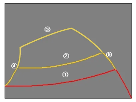
Operations for Guideline Steering Interlocking Indications
The guideline for steering interlocking trace is indicated by using the value of steering wheel angle periodically received by SVM ECU via C-CAN.
A combination of the rear area that displays of the rear mode (two-split mode) and the expected car movement trace displayed on the wide view is displayed.
| 1. |
View modes for guideline steering interlocking indications
|
| 2. |
Specifications for guideline steering interlocking trace lines
|
SVM System
| 1. |
SVM Video Output The SVM ECU displays the images from four installed cameras after passing the distortion correction and image synthesis steps and then displays the steering assist guidelines in analog format. |
| 2. |
SVM Switch The signals are input for control in forward display mode when the switch is ON. |
| 3. |
Ignition Input The SVM ECU displays video only on IGN2 ON and limits video output to SVM OFF when IGN2 is OFF. In order to check whether the IGN2 is ON, the SVM ECU uses the signals to the IGN pin or it uses the M-CAN messages routed to the C-CAN from the IGPM (Gateway). |
| 4. |
Switch Indicator Output The SVM ECU outputs the power of the LED on the SVM switch in PWM waveform to notify the driver whether or not the SVM switch is pressed. |
| 5. |
Chassis CAN Input (C-CAN) The SVM ECU receives the vehicle status data through the C-CAN and determines whether or not to perform key operations of the SVM. |
| 6. |
Multimedia CAN Input / Output The related information is processed after receiving M-CAN signals routed from the ICU to the C-CAN. The routed M-CAN signals are exchanged for data transmission and reception as follows: |
Repair procedures
| Inspection |
Tolerance Compensation
Tolerance compensation compensates for the error margins of surround view video that occur due to the installation tolerance when the four cameras that comprise the SVM system are installed.
Tolerance compensation must be carried out when the following actions are performed:
| – |
When removing and installing a wide camera. |
| – |
When conducting a body task such as the trunk task that causes the focus of the wide camera to change. |
| – |
When replacing the door mirror with a wide camera. |
| – |
When replacing the surround view monitoring unit. |
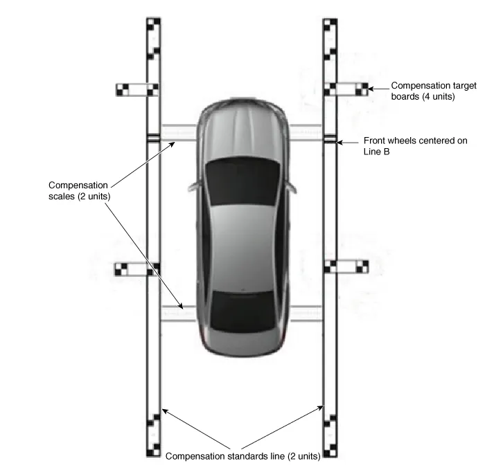
Tolerance Compensation Environments
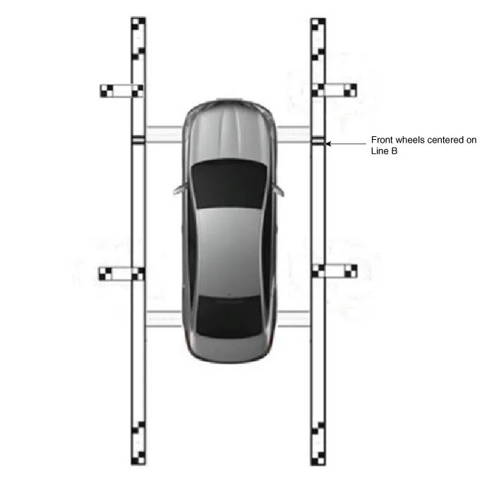
The Procedure of Manual Tolerance Compensation
| 1. |
Prepare in advance as below.
|
| 2. |
Before entering tolerance compensation mode, to check normal operation of SVM ECU and cameras, perform the following.
|
| 3. |
Install two compensation scales, two compensation reference line boards, and four compensation target boards around the vehicle by referring to the manual provided with the tools.
|

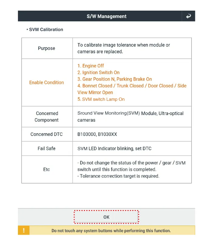
| 4. |
Maintain ignition "ON" with vehicle stopped, check that the gear is in P, and engage parking brake even on flat ground. |
| 5. |
Perform work with SVM switched "ON". |
| 6. |
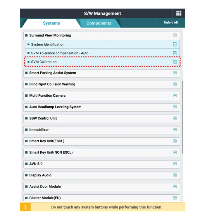
Connect the KDS to vehicle. |
| 7. |
Select vehicle model and system. |
| 8. |
Enter additional function in KDS. |
| 9. |
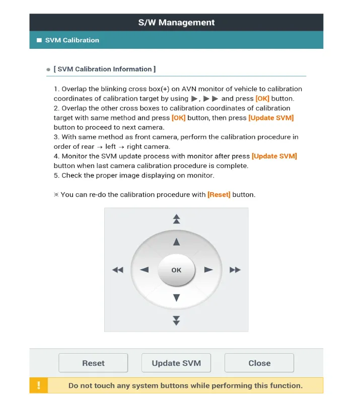
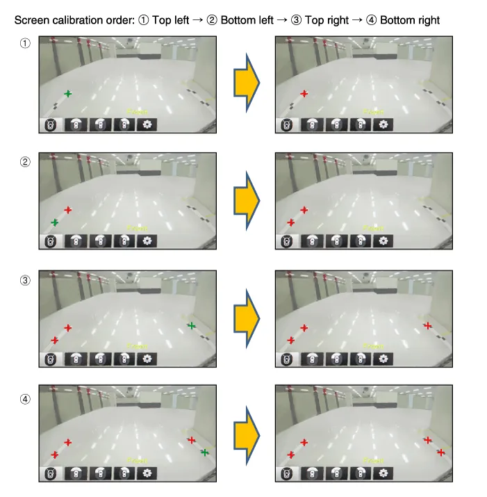
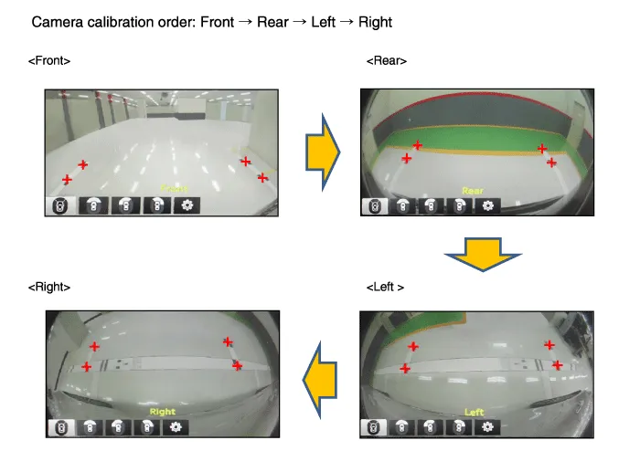
Perform SVM manual tolerance compensation as shown on KDS diagnostic device.
|
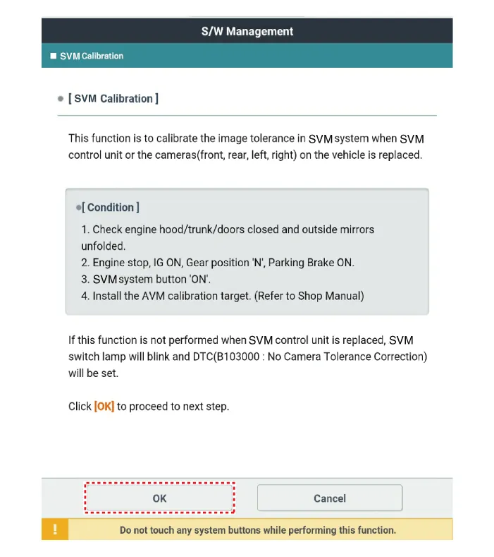
| 10. |
To confirm completion of calibration, check the vehicle and calibration line on AVN monitor and click [OK]. If calibration has not been properly performed, click [Cancel] and reenter calibration points. |
Components and components location Components Location 1. Rear view camera 2. Display audio/AVN head unit 3. Steering angle sensor Description and operation Description • The system displays the rear of the vehicle to assist the driver of potential hazards, it receives vehicle rear side image signal from the rear view monitor and displays it on monitor.
Schematic diagrams Connector and Terminal function Repair procedures Removal 1. Disconnect the negative (-) battery terminal.
Other information:
Kia Optima DL3 2019-2026 Service and Repair Manual: Integrated Memory Seat (IMS) Unit
Specifications Specifications Item Specifications Rated voltage DC 12 V Operating voltage DC 9 - 16 V Operating temperature range -22 to 167°F (-30 to 75°C) Dark current Max.
Kia Optima DL3 2019-2026 Service and Repair Manual: Intake Actuator
Components and components location Components Location 1. Intake actuator Description and operation Description The intake actuator is located at the blower unit. It regulates the intake door by a signal from the control unit.
Categories
- Manuals Home
- Kia Optima Owners Manual
- Kia Optima Service Manual
- Body (Interior and Exterior)
- Headlamps
- Lift And Support Points
- New on site
- Most important about car
