Kia Optima DL3: Surround View Monitor (SVM) / Surround View Monitor (SVM) Camera
Schematic diagrams
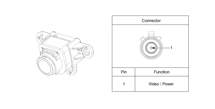
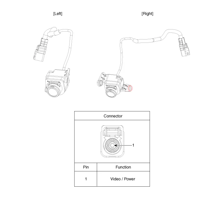
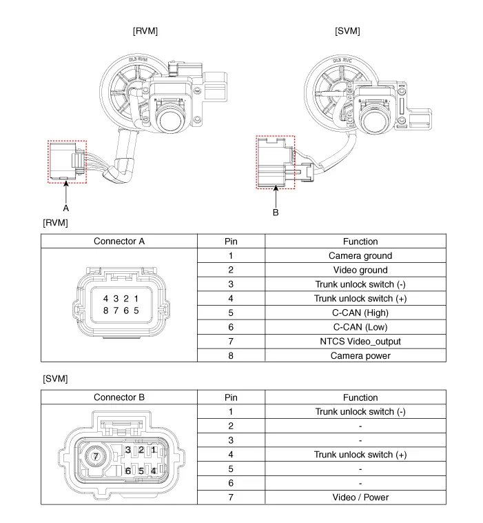
| Connector and Terminal function |
Front View Camera
Side View Camera
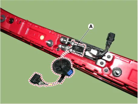
Rear View Camera
Repair procedures
| Removal |
In case of bad quality or poor focus, be sure to check the camera lens surface condition and foreign materials. |

Front View Camera
| 1. |
Disconnect the negative battery terminal. |
| 2. |
Remove the front bumper assembly. (Refer to Body - "Front Bumper Assembly") |
| 3. |
Disconnect the front view camera connector (A).
|
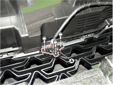
| 4. |
Remove the front view camera (A) after loosening the mounting screws.
|
Side View Camera
| 1. |
Disconnect the negative (-) battery terminal. |
| 2. |
Remove the outside rear view mirror scalp and housing cover. (Refer to Body - "Outside Rear View Mirror") |
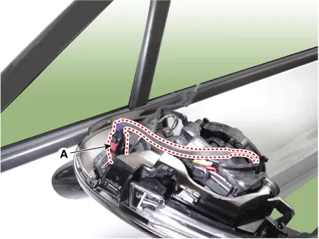
| 3. |
Disconnect the side view camera connector (A).
|
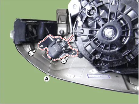
| 4. |
Remove the side view camera (A) after loosening the screws.
|
Rear View Camera
| 1. |
Disconnect the negative (-) battery terminal. |
| 2. |
Remove the center rear combination lamp. (Refer to Body Electrical System - "Rear Combination Lamp") |
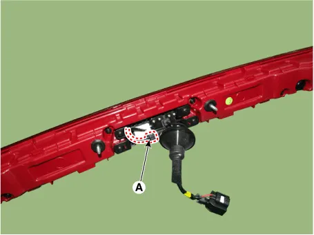
| 3. |
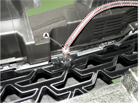
Disconnect the trunk switch connector (A).
|
| 4. |
Remove the rear view camera (A) after loosening the screws.
|
| Installation |
| 1. |
Install in the reverse order of removal. |
Schematic diagrams Connector and Terminal function Repair procedures Removal 1. Disconnect the negative (-) battery terminal.
Schematic diagrams Connector and Terminal Function Pin Function Pin Function 1 PAS mode switch 13 SVM mode indicator 2 PAS mode indicator 14 SVM mode switch 3 - 15 - 4 Detent 16 Ground 5 EPB switch1 17 EPB switch2 6 EPB switch3 18 EPB switch4 7 - 19 - 8 - 20 IGN1 9 Battery (+) 21 illumination (+) 10 - 22 - 11 ISG mode indicator 23 illumination (-) 12 ISG mode switch 24 Auto hold mode Repair procedures Removal • When prying with a flat-tip screwdriver or using a prying trim tool, wrap protective tap around the tool and related parts to prevent damage.
Other information:
Kia Optima DL3 2019-2026 Service and Repair Manual: Power Door Lock Module
Repair procedures Inspection When prying with a flat-tip screwdriver or use a prying trim tool, wrap it with protective tape, and apply protective tape around the related parts, to prevent damage.
Kia Optima DL3 2019-2026 Service and Repair Manual: Heater & A/C Control Unit (DATC)
Components and components location Components Connector Pin NO Funtion Pin NO Funtion 1 Ground 9 Ground 2 ILL- 10 - 3 - 11
Categories
- Manuals Home
- Kia Optima Owners Manual
- Kia Optima Service Manual
- Timing Chain
- Body Electrical System
- Suspension System
- New on site
- Most important about car
