Kia Optima DL3: Engine Electrical System
Service data
| Service Data |
| Ignition System |
Ignition Coil
|
Item |
Specification |
|
Primary Coil Resistance (Ω) |
0.75 ± 15% [20°C (68°F)] |
|
Secondary Coil Resistance (kΩ) |
5.9 ± 15% [20°C (68°F)] |
Spark Plug
|
Item |
Specification |
|
|
Type |
UNLEADED |
SILZKR7B11 |
|
LEADED |
SILZKR7B8 |
|
|
Gap |
UNLEADED |
1.0 - 1.1 mm (0.0393 - 0.0433 in.) |
|
LEADED |
0.7 - 0.8 mm (0.0275 - 0.0314 in.) |
|
| Charging System |
Alternator
|
Item |
Specification |
|
|
Rated voltage |
13.5V, 120A |
|
|
Speed in use |
1,000 - 18,000 rpm |
|
|
Voltage regulator |
IC Regulator built-in type |
|
|
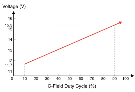
Regulator Setting Voltage |
External mode |
Refer to below graph |
|
Internal mode |
14.55 ± 0.3V |
|
|
Temperature Gradient |
External mode |
0 ± 3 mV / °C |
|
Internal mode |
-3.5 ± 2mV / °C |
|
Battery
▶CMF68L-DIN
|
Item |
Specification |
|
Model type |
CMF68L-DIN |
|
Capacity [20HR/5HR] (AH) |
68 / 54 |
|
Cold Cranking Amperage (A) |
600 (SAE / EN) |
|
Reserve Capacity (Min) |
113 |
|

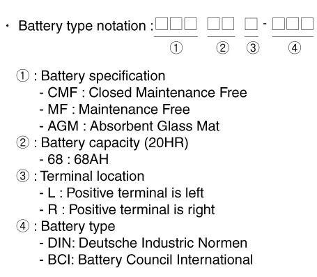
BCI Type
DIN Type
AGM DIN Type
|
| Starting System |
Starter
|
Item |
Specification |
|
|
Rated voltage |
12V, 1.2 kW |
|
|
The number of pinion teeth |
13 |
|
|
Performance [No-load, 11V] |
Ampere |
70A |
|
Speed |
Min. 2,400 rpm |
|
Components and components location Components 1. Intake camshaft 2. Exhaust camshaft 3. Intake CVVT assembly 4.
Description and operation Description Ignition timing is controlled by the electronic control ignition timing system. The standard reference ignition timing data for the engine operating conditions are pre-pro grammed in the memory of the ECM (Engine Control Module).
Other information:
Kia Optima DL3 2019-2026 Service and Repair Manual: Power Windows
Components and components location Component Location 1. Power window main switch 2. Rear window main switch 3. Front power window motor 4. Rear power window motor Description and operation Description Power Window Safety Function When the driver or passenger p
Kia Optima DL3 2019-2026 Service and Repair Manual: Rear Glass Defogger
C
Categories
- Manuals Home
- Kia Optima Owners Manual
- Kia Optima Service Manual
- Engine Mechanical System
- Motor Driven Power Steering
- Lift And Support Points
- New on site
- Most important about car
