Kia Optima DL3: Lighting System / Hazard Lamp Switch
Schematic diagrams
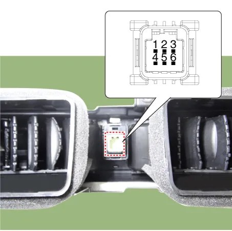
| Connector and Terminal Function |
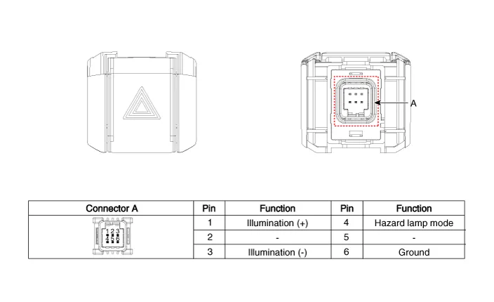
Repair procedures
| Removal |
| 1. |
Disconnect the negative battery terminal. |
| 2. |
Remove the crash pad garnish [RH]. (Refer to Body - "Crash Pad Garnish") |
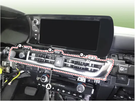
| 3. |
Remove the center air vent garnish (A) by loosening the mounting screws.
|
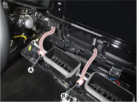
| 4. |
Disconnect the start/stop button connector (A) and hazard lamp switch connector (B).
|
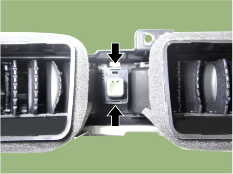
| 5. |
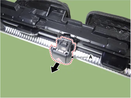
Remove the hazard lamp switch (A) by pressing the hooks.
|
| Installation |
| 1. |
Install in the reverse order of removal. |
| Inspection |
| 1. |
Disconnect the negative battery terminal. |
| 2. |
Remove the crash pad garnish [RH]. (Refer to Body - "Crash Pad Garnish") |
| 3. |
Remove the center air vent garnish (A) by loosening the mounting screws.
|
| 4. |
Disconnect the start/stop button connector (A) and hazard lamp switch connector (B).
|
| 5. |
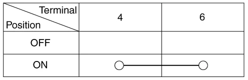
Check for continuity between the terminals.
|
Repair procedures Removal Front Fog Lamp 1. Disconnect the negative battery terminal. 2. Remove the front bumper assembly.
Components and components location Component Location 1. Low beam 2. High beam 3. Daytime Running Light / Position lamp 4.
Other information:
Kia Optima DL3 2019-2026 Service and Repair Manual: Panorama Sunroof Motor
Schematic diagrams Connector and Terminal Function Repair procedures Inspection 1. Disconnect the negative battery terminal. 2. Remove the rear pillar trim [LH]. (Refer to Body - "Rear Pillar Trim") 3.
Kia Optima DL3 2019-2026 Service and Repair Manual: Heater Control Unit
Components and components location Components Connector Pin Function [Connector A] Pin NO Funtion Pin NO Funtion 1 Ground 11 Ground 2 Clean signal 12 -
Categories
- Manuals Home
- Kia Optima Owners Manual
- Kia Optima Service Manual
- Motor Driven Power Steering
- Suspension System
- Rear Brake Disc
- New on site
- Most important about car
