Kia Optima DL3: Engine Control System / Knock Sensor (KS)
Specifications
| Specification |
|
Item |
Specification |
|
Capacitance (pF) |
850 - 1,150 |
Description and operation
| Description |
| • |
Knocking is a condition characterized by undesirable vibration and noise and can cause engine damage. |
| • |
Knock Sensor (KS) is installed on the cylinder block and senses engine knocking. |
| • |
When knocking occurs, the vibration from the cylinder block is applied as pressure to the piezoelectric element. At this time, this sensor transfers the voltage signal higher than the specified value to the ECM and the ECM retards the ignition timing. |
| • |
If the knocking disappears after retarding the ignition timing, the ECM will advance the ignition timing. This sequential control can improve engine power, torque and fuel economy. |

Components and components location
| Components Location |
| 1. Knock Sensor (KS) |
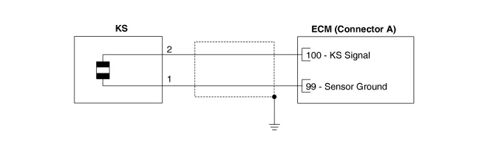
Schematic diagrams
| Circuit Diagram |
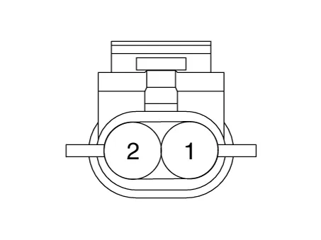
Harness Connector
Repair procedures
| Inspection |
| 1. |
The engine control system can be more quickly diagnosed for troubles by using the vehicle diagnostic system (KDS). (Refer to "DTC guide") KDS provides the following information.
|
| Component Inspection |
| 1. |
Turn the ignition switch OFF. |
| 2. |
Disconnect the knock sensor connector. |
| 3. |
Measure resistance between the knock sensor terminals 1 and 2. |
| 4. |
Check that the resistance is within the specification.
|
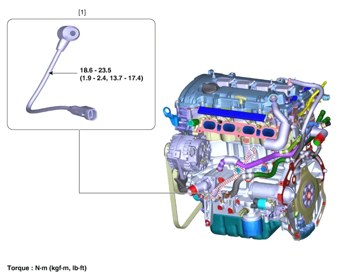
| Removal |
| 1. |
Disconnect the negative battery terminal. |
| 2. |
Remove the intake manifold. (Refer to Engine Mechanical System - "Intake Manifold") |
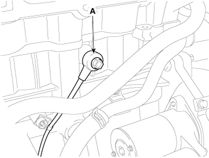
| 3. |
Remove the knock sensor (A) after loosening the mounting bolt.
|
| Installation |
|

| 1. |
Install in the reverse order of removal. |
Description and operation Description • Camshaft Position Sensor (CMPS) is a hall sensor, which detects the camshaft position by using a hall element.
Description and operation Description • Heated Oxygen Sensor (HO2S), consisting of zirconium and alumina, is installed on both upstream and downstream of the Manifold Catalytic Converter (MCC) to detect the air/fuel ratio and send it to the ECM.
Other information:
Kia Optima DL3 2019-2026 Service and Repair Manual: Power Windows
Components and components location Component Location 1. Power window main switch 2. Rear window main switch 3. Front power window motor 4. Rear power window motor Description and operation Description Power Window Safety Function When the driver or passenger p
Kia Optima DL3 2019-2026 Service and Repair Manual: Rear Glass Defogger
C
Categories
- Manuals Home
- Kia Optima Owners Manual
- Kia Optima Service Manual
- Rear Brake Disc
- Timing Chain
- Floor Console Assembly
- New on site
- Most important about car
