Kia Optima DL3: FCA warning message and system control / Collision Warning (1st warning)
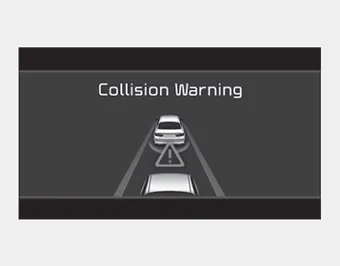
This warning message appears on the LCD display with a warning chime. Additionally, some vehicle system intervention occurs by the engine management system to help decelerate the vehicle.
- Your vehicle speed may decelerate moderately.
- The FCA system limitedly controls the brakes to preemptively mitigate impact in
a collision.
- It will operate if the vehicle speed is greater than 8 km/h (5 mph) and less than
or equal to 60 km/h (38 mph) on a forward vehicle. (Depending on the condition of
the vehicle ahead and the environment surrounding it, the possible maximum operating
speed may be reduced.)
Emergency braking (2nd warning)

This warning message appears on the LCD display with a warning chime. Additionally, some vehicle system intervention occurs by the engine management system to help decelerate the vehicle.
- The FCA system limitedly controls the brakes to preemptively mitigate impact
in a collision. The brake control is maximized just before a collision.
- It will operate if the vehicle speed is greater than 8 km/h (5 mph) and less than
or equal to 60 km/h (38 mph) on a forward vehicle. (Depending on the condition of
the vehicle ahead and the environment surrounding it, the possible maximum operating
speed may be reduced.)
The FCA system produces warning messages, warning alarms, and emergency braking based on the level of risk of a frontal collision, such as when a vehicle ahead suddenly brakes.
In an urgent situation, the FCA system applies the brakes. The FCA provides additional braking power for optimum braking performance, when the driver depresses the brake pedal.
Other information:
Kia Optima DL3 2019-2026 Service and Repair Manual: Rear Glass Defogger Switch
Repair procedures Inspection 1. In the body electrical system, failure can be quickly diagnosed by using the vehicle diagnostic system (KDS). The diagnostic system (KDS) provides the following information. (1) Self diagnosis : Checking failure and code number (DTC).
Kia Optima DL3 2019-2026 Service and Repair Manual: Washer Switch
R
Categories
- Manuals Home
- Kia Optima Owners Manual
- Kia Optima Service Manual
- Motor Driven Power Steering
- Identification Numbers
- Floor Console Assembly
- New on site
- Most important about car
