Kia Optima DL3: Driveshaft and axle / Rear Hub - Carrier
Components and components location
| Components |
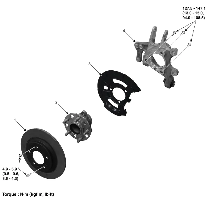
| 1. Rear brake disc 2. Hub bearing assembly |
3. Dust cover 4. Rear carrier |
Repair procedures
| Removal |
| 1. |
Disconnect the (-) battery terminal. |
| 2. |
Remove the rear wheel and tire. (Refer to Suspension System - "Wheel") |
| 3. |
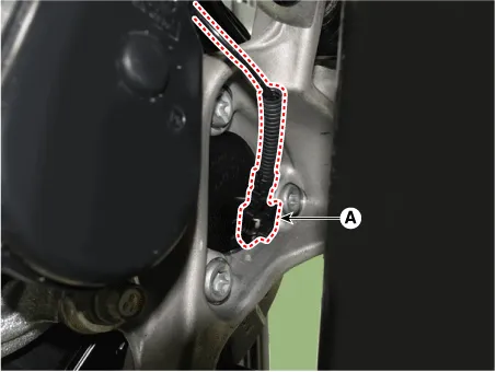
Disconnect the rear wheel speed sensor connector (A).
|
| 4. |
Remove the rear brake caliper assembly. (Refer to Brake System - "Rear Brake Caliper") |
| 5. |
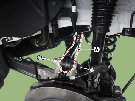
Loosen the rear trailing arm mounting nut from the rear axle.
|
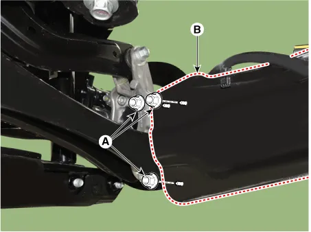
| 6. |
Loosen the rear lower arm mounting bolt and nut from the rear axle.
|

| 7. |
Loosen the rear assist arm mounting bolt and nut from the rear axle.
|
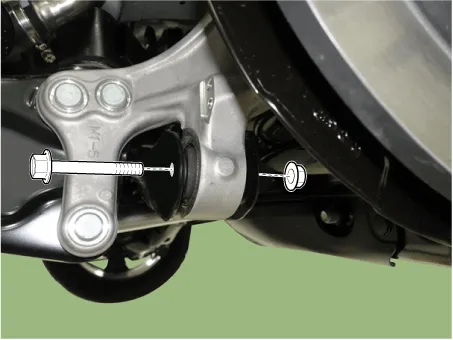
| 8. |
Loosen the rear upper arm mounting bolt and nut from the rear axle.
|
| Installation |
| 1. |
Install in the reverse order of removal. |
| 2. |
Check the rear alignment. (Refer to Suspension System - "Alignment") |
| Disassembly |
| 1. |
Loosen the screws and then remove the rear brake disc (A).
|
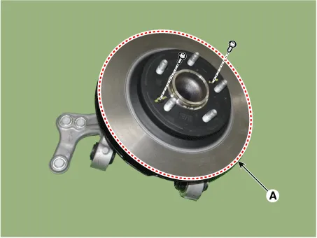
| 2. |
Loosen the hub bearing mounting bolts from the rear knuckle (A).
|

| Reassembly |
| 1. |
Assemble in the reverse order of disassembly. |
| Inspection |
| 1. |
Check the hub for cracks and the splines for wear. |
| 2. |
Check the brake disc for scoring and damage. |
| 3. |
Check the rear axle carrier for cracks. |
| 4. |
Check the bearing for cracks or damage. |
Components and components location Components 1. Front brake disc 2. Front hub assembly 3. Dust cover 4. Front knuckle Repair procedures Removal 1.
Other information:
Kia Optima DL3 2019-2026 Service and Repair Manual: Power Door Mirrors
C
Kia Optima DL3 2019-2026 Service and Repair Manual: Power Window Switch
Schematic diagrams Connector and Terminal Function Power Window Main Switch Pin Function 1 B-CAN (Low) 2 B-CAN (High) 3 Ground (Assist safety) 4 Assist safety 5
Categories
- Manuals Home
- Kia Optima Owners Manual
- Kia Optima Service Manual
- Body (Interior and Exterior)
- Steering System
- Suspension System
- New on site
- Most important about car
