Kia Optima DL3: Body Electrical System / Fuel Filler Door
Components and components location
| Components Location |
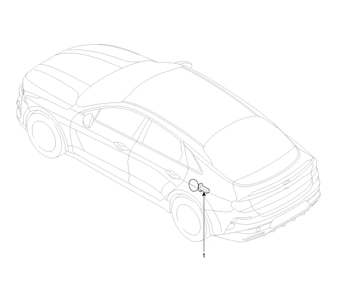
| 1. Fuel filler door unlock actuator
|
Components and components location Component Location 1. Integrated central control unit (ICU) Description and operation Description Integrated Central control Unit (ICU) combines both Smart Junction Block (SJB) and Integrated Gateway & Power Control Module (IGPM) System Block Diagram Function Item Function Function Switch input Receives switch inputs and then sends the switch status to each module through CAN message.
Repair procedures Removal 1. Disconnect the negative battery terminal. 2. Remvoe the fuel door housing.
Other information:
Kia Optima DL3 2019-2026 Service and Repair Manual: Room Lamp
Repair procedures Removal When removing with a flat-tip screwdriver or remover, wrap protective tape around the tools to prevent damage to components. 1.
Kia Optima DL3 2019-2026 Service and Repair Manual: Climate Control Air Filter
Description and operation Description The climate control air filter is located in the blower unit. It eliminates foreign materials and odor. The particle filter performs a role as an odor filter as well as a conventional dust filter to ensure comfortable interior environment.
Categories
- Manuals Home
- Kia Optima Owners Manual
- Kia Optima Service Manual
- Rear Brake Disc
- Engine Mechanical System
- Body (Interior and Exterior)
- New on site
- Most important about car
