Kia Optima DL3: Fuel Delivery System / Fuel Filter
Components and components location
| Component |

| 1. Plate Assembly 2. Clip 3. O-ring 4. Bracket 5. Fuel Reservoir Cup 6. Fuel Pump Filter 7. Fuel Pump & Tube Assembly |
8. O-ring 9. Spacer 10. Assist Pump 11. Clip 12. Fuel Pressure Regulator 13. Fuel Filter 14. Wiring |
Repair procedures
| Removal |
| 1. |
Remove the fuel pump module. (Refer to Fuel Delivery System - "Fuel Pump Module") |
| 2. |
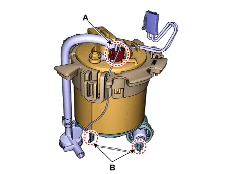
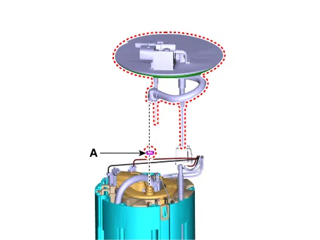
Disconnect the fuel pump motor connector (A) and fuel sender connector (B).
|

| 3. |
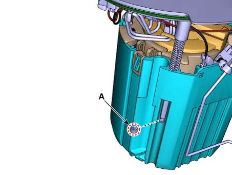
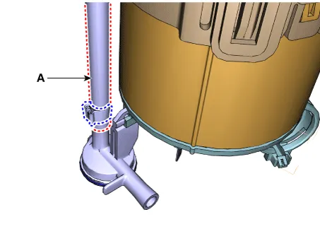
Remove the fuel feed tube quick-connector (B) after remove the clip (A).
|

| 4. |
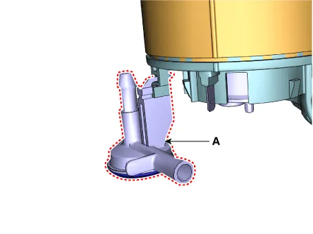
Remove the stopper (A) from the plate pipe.
|
| 5. |
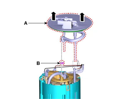
Remove the head assembly (A) and O-ring (B).
|
| 6. |
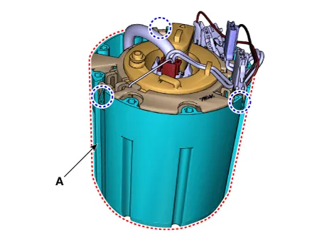
Remove the reservoir cup (A) after releasing the fixing hooks.
|
| 7. |
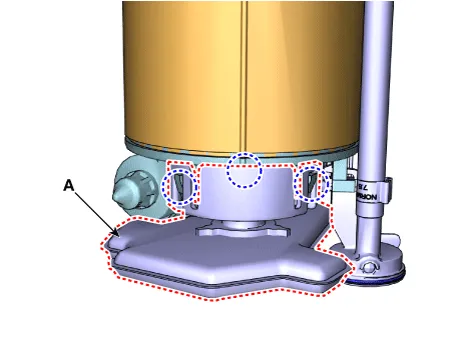
Remove the pump filter (A) after releasing the fixing hooks.
|
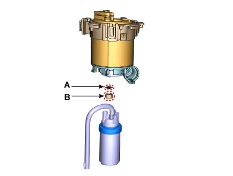
| 8. |
Remove the wiring from the fuel filter after disconnecting the fuel pump connector (A) and ground (B).
|
| 9. |
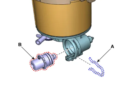
Remove the fuel pressure regulator (B) after removing the fixing clip (A).
|
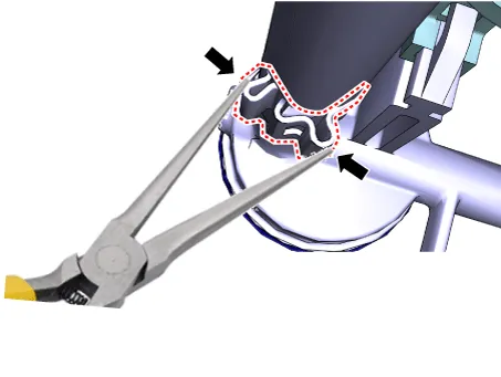
| 10. |
Disconnect the fuel pump hose (A) after releasing the clamp.
|
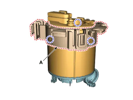
| 11. |
Remove the assist pump (A) after releasing the fixing hook.
|
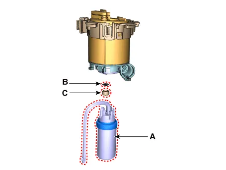
| 12. |
Remove the O-ring (B) and spacer (C) after removing the fuel pump & tube (A).
|
| 13. |
Remove the bracket (A) from the fuel filter.
|
| Installation |
| 1. |
Install in the reverse order of removal. |
|

Specifications Specification Items Specification Current (A) Max. 6.0 Supply Voltage (V) 12 Fuel Pressure bar 3.
Components and components location Component 1. Plate Assembly 2. Clip 3. O-ring 4. Fuel Reservoir Cup 5. Fuel Pump Filter 6.
Other information:
Kia Optima DL3 2019-2026 Service and Repair Manual: Integrated Body Control Unit (IBU)
Components and components location Component Location 1. Integrated Body Control Unit (IBU) Schematic diagrams Connector and Terminal Function [Non-Smart key] Pin Function Connector A Connector B
Kia Optima DL3 2019-2026 Service and Repair Manual: Smart Key Diagnostic
Repair procedures Inspection 1. In the body electrical system, failure can be quickly diagnosed by using the vehicle diagnostic system (KDS). The diagnostic system (KDS) provides the following information. (1) Self diagnosis : Checking failure and code number (DTC).
Categories
- Manuals Home
- Kia Optima Owners Manual
- Kia Optima Service Manual
- Motor Driven Power Steering
- Heating, Ventilation and Air Conditioning
- Timing Chain
- New on site
- Most important about car
