Kia Optima DL3: Fuel Delivery System / Fuel Pump & Tube Assembly
Components and components location
| Component |
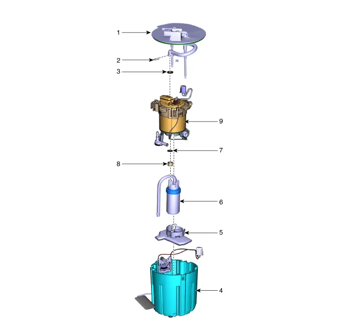
| 1. Plate Assembly 2. Clip 3. O-ring 4. Fuel Reservoir Cup 5. Fuel Pump Filter |
6. Fuel Pump & Tube Assembly
7. O-ring 8. Spacer 9. Fuel Filter |
Repair procedures
| Removal |
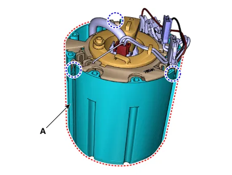
| 1. |
Remove the fuel pump module. (Refer to Fuel Delivery System - "Fuel Pump Module") |
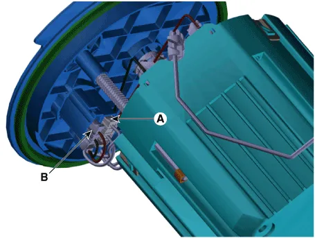
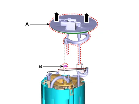
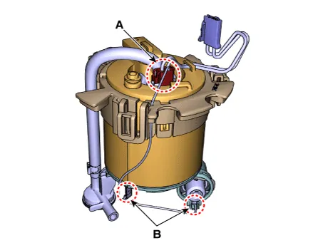
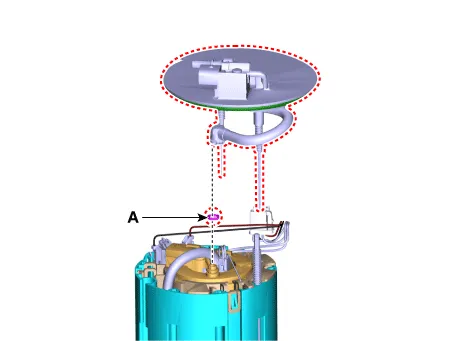
| 2. |
Disconnect the fuel pump motor connector (A) and fuel sender connector (B).
|
| 3. |
Remove the fuel feed tube quick-connector (B) after remove the clip (A).
|
| 4. |
Remove the stopper (A) from the plate pipe.
|
| 5. |
Remove the head assembly (A) and O-ring (B).
|
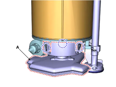
| 6. |
Remove the reservoir cup (A) after releasing the fixing hooks.
|
| 7. |
Remove the pump filter (A) after releasing the fixing hooks.
|
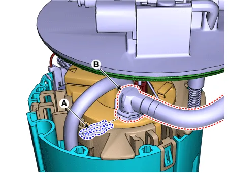
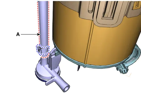
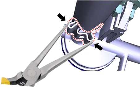
| 8. |
Disconnect the fuel pump hose (A) after releasing the clamp.
|
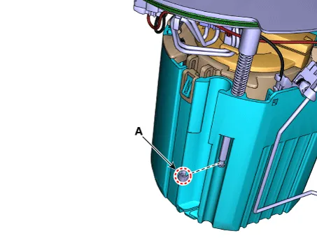
| 9. |
Remove the wiring from the fuel filter after disconnecting the fuel pump connector (A) and ground (B).
|
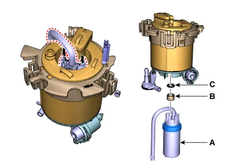
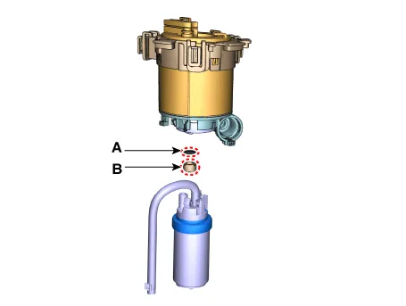
| 10. |
Remove the spacer (B) and O-ring (C) after removing the fuel pump & tube (A).
|
| Installation |
| 1. |
Install in the reverse order of removal. |
|

Components and components location Component 1. Plate Assembly 2. Clip 3. O-ring 4. Bracket 5. Fuel Reservoir Cup 6.
Components and components location Component 1. Fuel Sender Assembly 2. Fuel Pump Module Repair procedures Removal 1.
Other information:
Kia Optima DL3 2019-2026 Service and Repair Manual: Rheostat
Schematic diagrams Connector and Terminal Function Repair procedures Removal 1. Disconnect the negative battery terminal. 2. Remove the crash pad lower panel. (Refer to Body - "Crash Pad Lower Panel") 3.
Kia Optima DL3 2019-2026 Service and Repair Manual: Intake Actuator
Components and components location Components Location 1. Intake actuator Description and operation Description The intake actuator is located at the blower unit. It regulates the intake door by a signal from the control unit.
Categories
- Manuals Home
- Kia Optima Owners Manual
- Kia Optima Service Manual
- Restraint
- Engine Control / Fuel System
- Battery
- New on site
- Most important about car
