Kia Optima DL3: Fuel Delivery System / Fuel Sender
Components and components location
| Component |
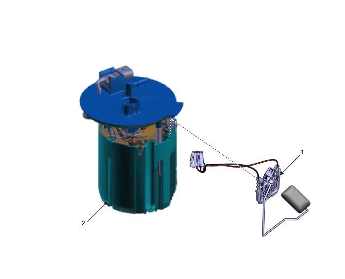
| 1. Fuel Sender Assembly |
2. Fuel Pump Module |
Repair procedures
| Removal |
| 1. |
Remove the fuel pump. (Refer to Fuel Delivery System - "Fuel Pump Module") |
| 2. |
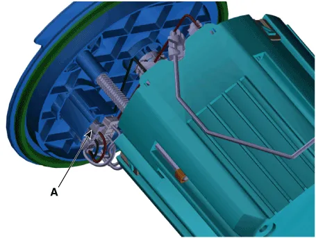
Disconnect the fuel sender connector (A).
|
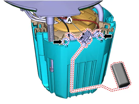
| 3. |
Remove the fuel sender assembly (A) after releasing the fixing hooks.
|
| Installation |
| 1. |
Install in the reverse order of removal. |
Components and components location Component 1. Plate Assembly 2. Clip 3. O-ring 4. Fuel Reservoir Cup 5. Fuel Pump Filter 6.
Components and components location Component 1. Plate Assembly 2. Clip 3. O-ring 4. Fuel Reservoir Cup 5.
Other information:
Kia Optima DL3 2019-2026 Service and Repair Manual: Overhead Console Lamp
Schematic diagrams Connector and Terminal Function [A Type] Connector A Pin E xcept Russia Region Russia only Function Function 1 Battery (+) Battery (+)
Kia Optima DL3 2019-2026 Service and Repair Manual: Power Mosfet
Description and operation Description It is installed to the DATC and adjusts the fan rpm by precisely controlling the voltage applied to the blower motor. Repair procedures Inspection 1. Turn the ignition switch ON.
Categories
- Manuals Home
- Kia Optima Owners Manual
- Kia Optima Service Manual
- Battery
- Steering System
- Automatic Transaxle System
- New on site
- Most important about car
