Kia Optima DL3: Fuel Delivery System / Fuel Pressure Regulator
Components and components location
| Component |
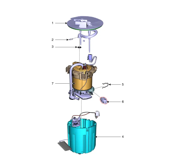
| 1. Plate Assembly 2. Clip 3. O-ring 4. Fuel Reservoir Cup |
5. Clip 6. Fuel Pressure Regulator 7. Fuel Filter |
Repair procedures
| Removal |
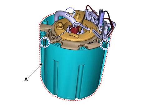
| 1. |
Remove the fuel pump module. (Refer to Fuel Delivery System - "Fuel Pump Module") |
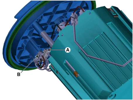
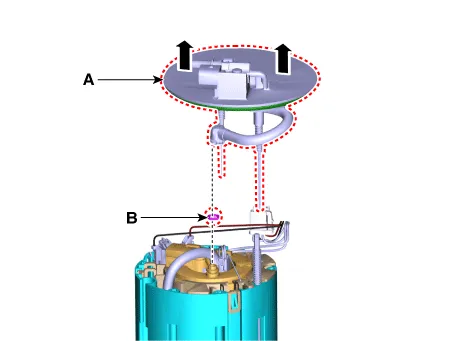
| 2. |
Disconnect the fuel pump motor connector (A) and fuel sender connector (B).
|
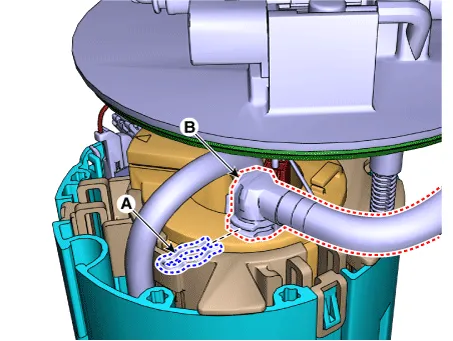
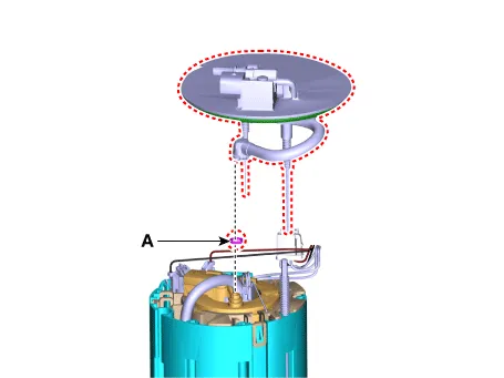
| 3. |
Remove the fuel feed tube quick-connector (B) after remove the clip (A).
|
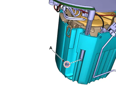
| 4. |
Remove the stopper (A) from the plate pipe.
|
| 5. |
Remove the head assembly (A) and O-ring (B).
|
| 6. |
Remove the reservoir cup (A) after releasing the fixing hooks.
|
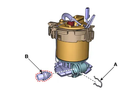
| 7. |
Remove the fuel pressure regulator (B) after removing the fixing clip (A).
|
| Installation |
| 1. |
Install in the reverse order of removal.
|

Components and components location Component 1. Fuel Sender Assembly 2. Fuel Pump Module Repair procedures Removal 1.
Components and components location Component 1. Filler-Neck Assembly 2. Fuel Tank Complete 3. Fuel Line Repair procedures Removal 1.
Other information:
Kia Optima DL3 2019-2026 Service and Repair Manual: Power Door Mirror Switch
Schematic diagrams Connector and Terminal Function Pin Function 1 B-CAN (Low) 2 B-CAN (High) 3 Ground (Assist safety) 4 Assist safety 5 LIN (For IMS)
Kia Optima DL3 2019-2026 Service and Repair Manual: Condenser
Components and components location Components Location 1. Condenser Repair procedures Inspection 1. Check the condenser fins for clogging and damage. If clogged, clean them with water, and blow them with compressed air.
Categories
- Manuals Home
- Kia Optima Owners Manual
- Kia Optima Service Manual
- Floor Console Assembly
- Motor Driven Power Steering
- Engine Control / Fuel System
- New on site
- Most important about car
