Kia Optima DL3: Fuel Delivery System / Injector
Specifications
| Specification |
|
Item |
Specification |
|
Coil Resistance (Ω) |
14.5 [20°C(68°F)] |
Description and operation
| Description |
| • |
Based on information from various sensors, the ECM can calculate the fuel amount to be injected. |
| • |
The fuel injector is a solenoid-operated valve and the fuel injection amount is controlled by length of injection time. |
| • |
The ECM controls each injector by grounding the control circuit. When the ECM energizes the injector by grounding the control circuit, the circuit voltage should be low (theoretically 0V) and the fuel is injected. When the ECM de-energizes the injector by opening control circuit, the fuel injector is closed and circuit voltage should momentarily peak. |
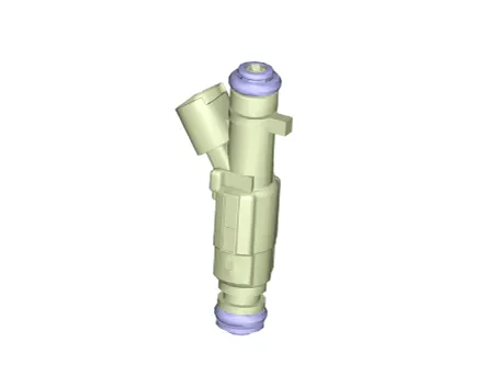
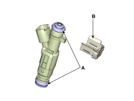
Components and components location
| Components |
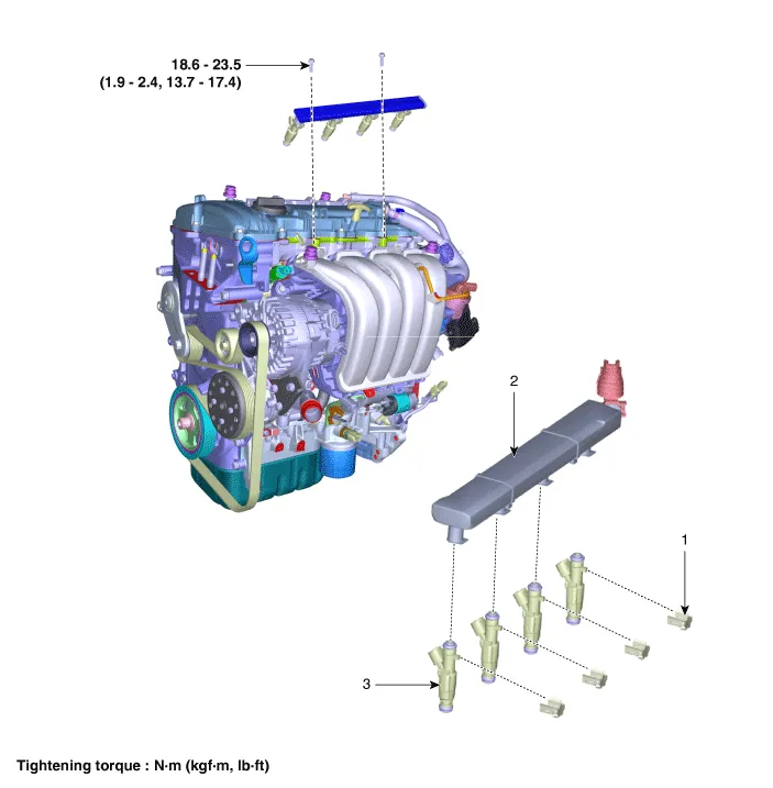
| 1. Clip 2. Delivery Pipe |
3. Injector |
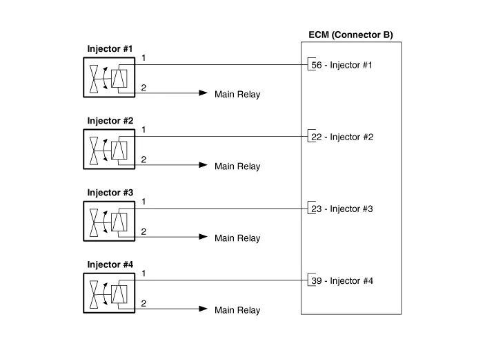
Schematic diagrams
| Circuit Diagram |
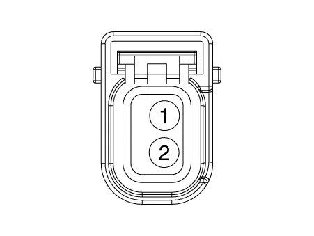
Harness Connector
Repair procedures
| Inspection |
| 1. |
In the engine control system, failure can be quickly diagnosed by using the vehicle diagnostic system (KDS).
|
| Components Inspection |
| 1. |
Turn the ignition switch OFF. |
| 2. |
Disconnect the injector connector. |
| 3. |
Measure resistance between the injector terminals 1 and 2. |
| 4. |
Check that the resistance is within the specification.
|
| Removal |
| 1. |
Remove the injector from the delivery pipe. (Refer to Fuel Delivery System - "Injector") |
| Installation |
| 1. |
Install in the reverse order of removal. |
Note the followings when mounting the injector on the delivery pipe.
|

Components and components location Components 1. Clip 2. Delivery Pipe 3. Injector Repair procedures Removal 1.
Service data Service data Automatic Transaxle Item Specification Transaxle model A6MF1-2 Engine model G 2.
Other information:
Kia Optima DL3 2019-2026 Service and Repair Manual: Temperature Control Actuator
Components and components location Components Location 1. Temperature control actuator [LH] 2. Temperature control actuator [RH] Description and operation Description The temperature control actuator is located at the heater unit.
Kia Optima DL3 2019-2026 Service and Repair Manual: Intake Actuator
Components and components location Components Location 1. Intake actuator Description and operation Description The intake actuator is located at the blower unit. It regulates the intake door by a signal from the control unit.
Categories
- Manuals Home
- Kia Optima Owners Manual
- Kia Optima Service Manual
- Timing Chain
- Brake System
- Lift And Support Points
- New on site
- Most important about car
