Kia Optima DL3: Advanced Driver Assistance System (ADAS) / Parking Collision-Avoidance Assist (PCA)
Components and components location
| Component Location |
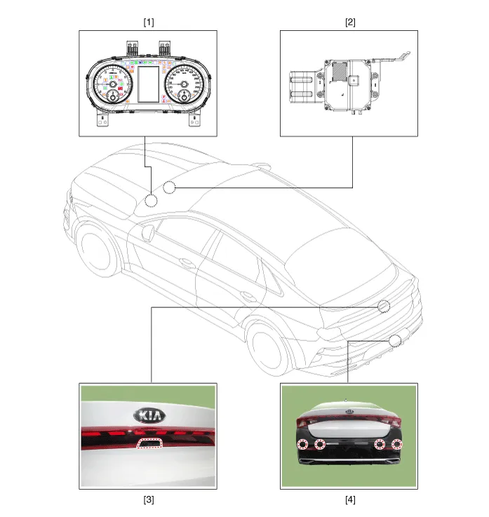
| 1. Cluster (USM) 2. Parking collision-avoidance assist (PCA) Unit |
3. Rear view camera 4. Parking distance warning-reverse (PDW-R) sensor |
Description and operation
| Description |
| • |
Parking Collision-Avoidance Assist-Reverse (PCA-R) : When the vehicle is in reverse, in order to prevent collosion and reduce possible damage, the system warns to the driver or controls the brake in case of danger of collision with pedestrians or objects. |
| 1. |
PCA-R activation condition
|
| 2. |
PCA-R Operation
|
| 3. |
System components
|
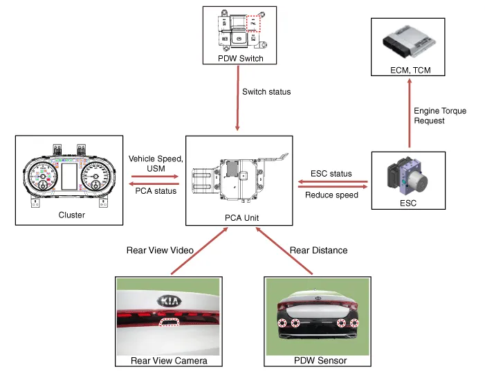
| 4. |
System block diagram
|

Schematic diagrams
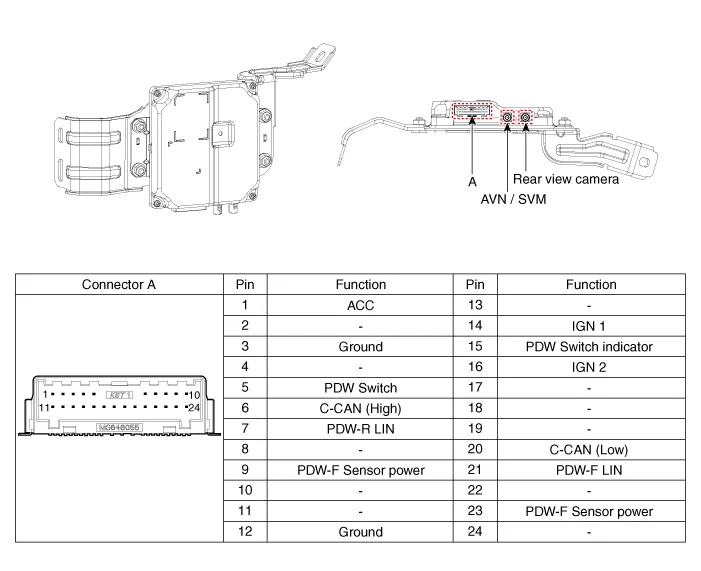
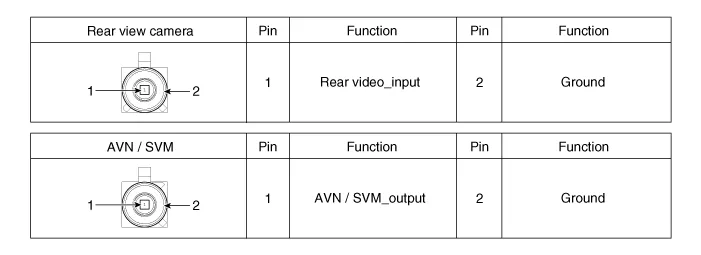
| Connector and Terminal function |
Parking Collision-Avoidance Assist (PCA-R) Unit
Repair procedures
| Inspection |
| 1. |
In the body electrical system, failure can be quickly diagnosed by using Kia Diagnostic System (KDS). The diagnostic system (KDS) provides the following information.
|
| Removal |
Parking Collision-Avoidance Assist-Reverse (PCA-R) Unit
| 1. |
Disconnect the negative (-) battery terminal. |
| 2. |
Remove the crash pad lower panel. (Refer to Body - "Crash Pad Lower Panel") |
| 3. |
Remove the knee airbag (KAB) module. (Refer to Body - "Knee Airbag (KAB) Module") |
| 4. |
Remove the driver side shower duct (A) after loosening the screw.
|
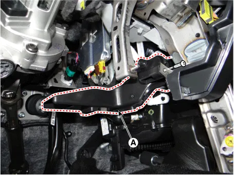
| 5. |
Disconnect the PCA-R unit connectors (A).
|
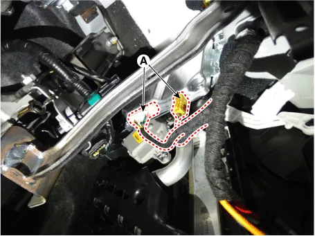
| 6. |
Remove the PCA-R unit (A) after loosening the mounting nuts.
|

Rear View Camera
| 1. |
Remove the rear view camera. (Refer to Rear View Monitor (RVM) - "Repair procedures") |
Parking Distance Warning-Reverse Sensor
| 1. |
Remove the PDW-R sensor. (Refer to Parking Distance Warning (PDW) - "Parking Distance Warning (PDW) Sensor") |
| Installation |
| 1. |
Install in the reverse order of removal. |
| 2. |
When replacing PCA unit with a new one, perform the variant coding procedure by using the KDS.
|

Schematic diagrams Connector and Terminal Function Pin Function Pin Function 1 PAS mode switch 13 SVM mode indicator 2 PAS mode indicator 14 SVM mode switch 3 - 15 - 4 Detent 16 Ground 5 EPB switch1 17 EPB switch2 6 EPB switch3 18 EPB switch4 7 - 19 - 8 - 20 IGN1 9 Battery (+) 21 illumination (+) 10 - 22 - 11 ISG mode indicator 23 illumination (-) 12 ISG mode switch 24 Auto hold mode Repair procedures Inspection 1.
Other information:
Kia Optima DL3 2019-2026 Service and Repair Manual: Integrated Memory Seat (IMS) Unit
Specifications Specifications Item Specifications Rated voltage DC 12 V Operating voltage DC 9 - 16 V Operating temperature range -22 to 167°F (-30 to 75°C) Dark current Max.
Kia Optima DL3 2019-2026 Service and Repair Manual: Air Conditioning System
General safety information and caution Instructions (R-134a) When Handling Refrigerant 1. R-134a liquid refrigerant is highly volatile. A drop on the skin of your hand could result in localized frostbite. When handling the refrigerant, be sure to wear gloves.
Categories
- Manuals Home
- Kia Optima Owners Manual
- Kia Optima Service Manual
- Suspension System
- Steering System
- Timing Chain
- New on site
- Most important about car
