
Kia Optima DL3: Rear Suspension System / Rear Coil Spring
Repair procedures
| Removal |
| 1. |
Disconnect the (-) battery terminal. |
| 2. |
Remove the rear wheel and tire. (Refer to Tires/Wheels - "Wheel") |
| 3. |
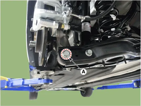
Loosen the bolt and nut (A) and then remove the rear lower arm from the rear axle.
|

| 4. |
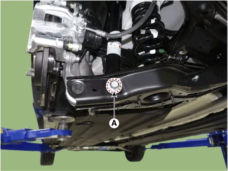
Loosen the bolt and nut (A) and remove the rear shock absorber from the rear lower arm.
|
| 5. |
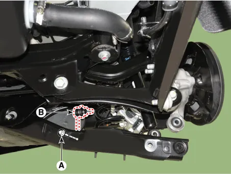
Loosen the bolt and nut (A) and then disconnect the rear stabilizer link from the rear lower arm.
|
| 6. |
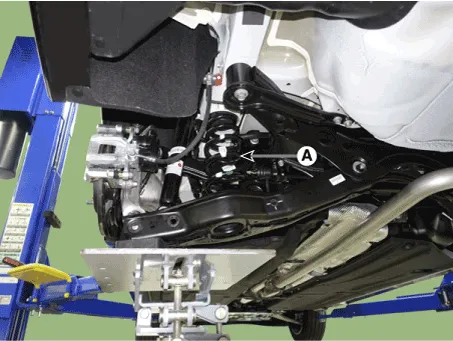
Remove the rear coil spring (A).
|
| Inspection |
| 1. |
Check the spring for distortion, aging or damage. |
| 2. |
Check the spring upper pad and lower pad for aging or damage. |
| Installation |
| 1. |
Install in the reverse order of removal. |
| 2. |
Check the alignment. (Refer to Suspension System - "Alingment") |
Components and components location Components Repair procedures Removal 1. Disconnect the (-) battery terminal.
Repair procedures Removal 1. Disconnect the (-) battery terminal. 2. Remove the rear wheel and tire.
Other information:
Kia Optima DL3 2019-2026 Service and Repair Manual: Heating, Ventilation and Air Conditioning
Service data Service Data Air Conditioner ltem Specification Compressor Type 6SAS14 Oil type & Capacity ND-OIL 12 80 ± 10 cc (2.82 ± 0.
Kia Optima DL3 2019-2026 Service and Repair Manual: Air Conditioning System
General safety information and caution Instructions (R-134a) When Handling Refrigerant 1. R-134a liquid refrigerant is highly volatile. A drop on the skin of your hand could result in localized frostbite. When handling the refrigerant, be sure to wear gloves.
Categories
- Manuals Home
- Kia Optima Owners Manual
- Kia Optima Service Manual
- Cooling System
- Motor Driven Power Steering
- Heating, Ventilation and Air Conditioning
- New on site
- Most important about car
