Kia Optima DL3: Rear Suspension System / Rear Shock Absorber
Components and components location
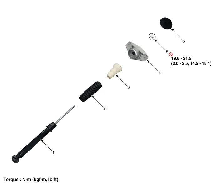
| Components |
Repair procedures
| Removal |
| 1. |
Disconnect the (-) battery terminal. |
| 2. |
Remove the rear wheel and tire. (Refer to Tires/Wheels - "Wheel") |
| 3. |
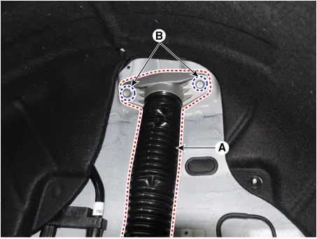
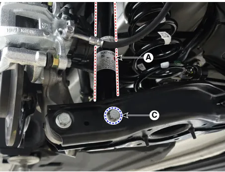
Remove the rear shock absorber (A). after loosening the bolts.
|
| Installation |
| 1. |
Install in the reverse order of removal. |
| 2. |
Check the alignment. (Refer to Suspension System - "Alingment") |
| Disassembly |
| 1. |
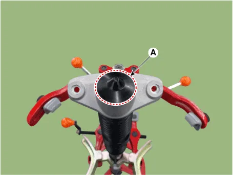
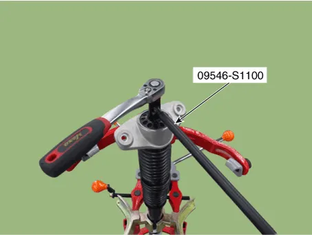
Remove the lock nut cover (A).
|
| 2. |
Using the special tool (09546-S1100), install the self locking nut.
|
| 3. |
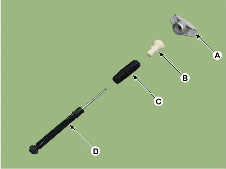
Separate the bracket assembly (A), bumper rubber (B), dust cover (C), shock absorber (D).
|
| Inspection |
| 1. |
Check the rubber parts for damage or deterioration. |
| 2. |
Check the shock absorber for abnormal resistance or unusual sounds.
|
| Disposal |
| 1. |
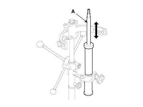
Fully extend the shock absorber rod. |
| 2. |
Drill a hole to remove gas from the cylinder.
|


| Reassembly |
| 1. |
To reassembly, reverse the disassembly procedure. |
| 2. |
Using SST(09546-S1100), install the lock nut.
|

| 3. |
Install the lock nut cover (A).
|
Components and components location Components and Components Location 1. Trailing arm 2. Rear shock absorber 3. Rear suspension 4.
Repair procedures Removal 1. Disconnect the (-) battery terminal. 2. Remove the rear wheel and tire.
Other information:
Kia Optima DL3 2019-2026 Service and Repair Manual: Smart Key
Repair procedures Adjustment Smart Key Code Saving 1. Connect the VCI II in driver side crash pad lower panel, turn the power on KDS. 2. Select the vehicle model and then do "Smart key code saving".
Kia Optima DL3 2019-2026 Service and Repair Manual: Heater Unit
Components and components location Component Location 1. Heater unit assembly Compoents 1. Mode control actuator 2. Temperature control actuator [LH] 3. PTC Heater dummy 4.
Categories
- Manuals Home
- Kia Optima Owners Manual
- Kia Optima Service Manual
- Body (Interior and Exterior)
- Charging System
- Timing Chain
- New on site
- Most important about car
