Kia Optima DL3: Front Suspension System / Sub Frame
Repair procedures
| Removal |
| 1. |
Disconnect the (-) battery terminal. |
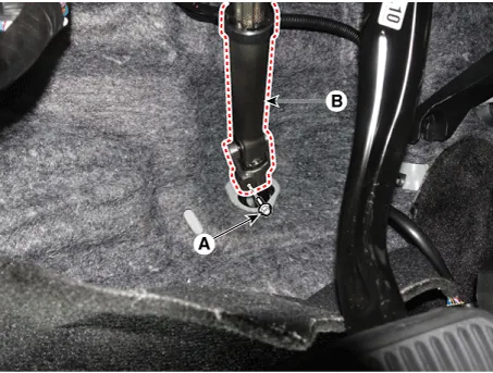
| 2. |
Loosen the bolt (A) and remove the universal joint (B).
|

| 3. |
Remove the front wheel and tire. (Refer to Tires/Wheels - "Wheel") |
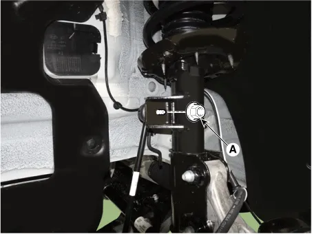
| 4. |
Disconnect the stabilizer link with the front strut assembly after loosening the nut (A).
|
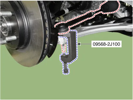
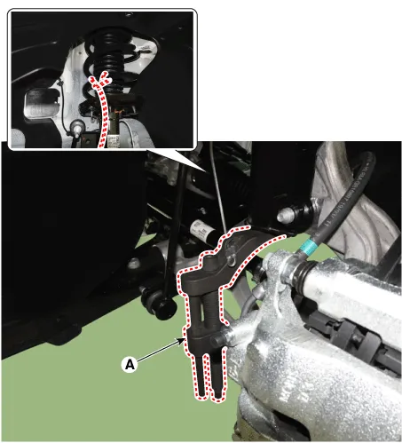
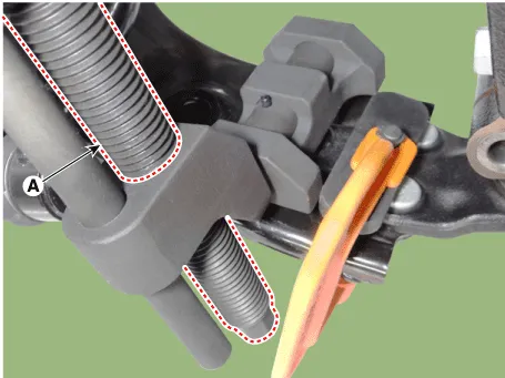
| 5. |
Disconnect the tie rod end ball joint from the knuckle by using the SST (09568-2J100).
|

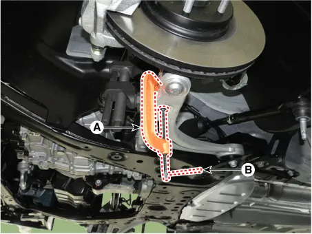
| 6. |
Loosen the lower arm mounting nut (A).
|
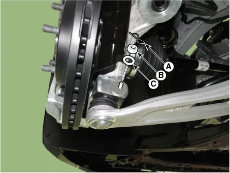
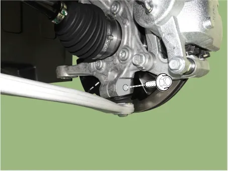
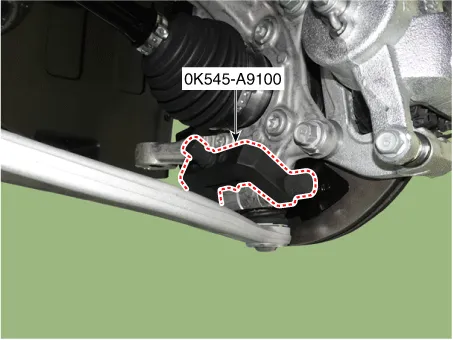
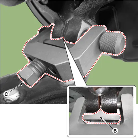
| 7. |
Disconnect lower arm ball joint from the knuckle by using the SST (0K545-A9100).
|
| 8. |
Remove the engine room under cover. G 2.0 NU MPI (Refer to Engine Mechanical System - "Engine Room Under Cover") G 2.5 GDI THETA II (Refer to Engine Mechanical System - "Engine Room Under Cover") |
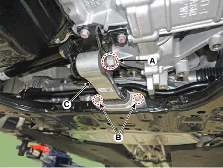
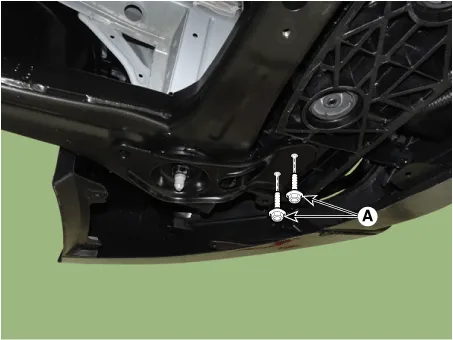
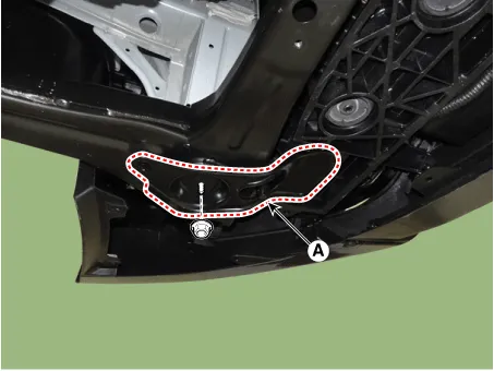
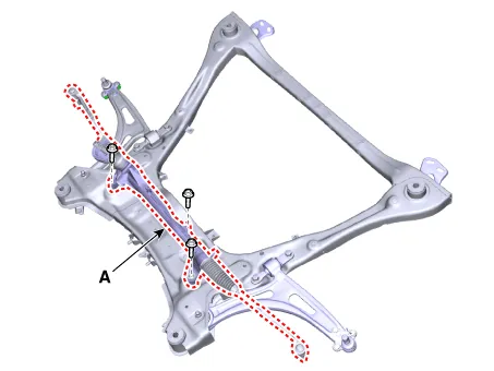
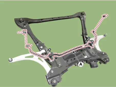
| 9. |
Separate the roll rod bracket (C) after loosening the bolts (A), (B).
|
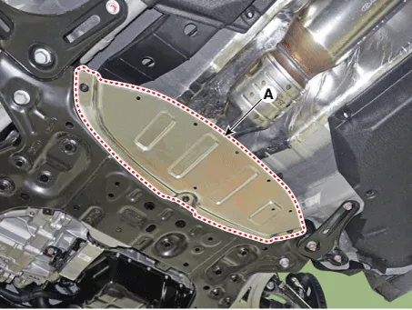
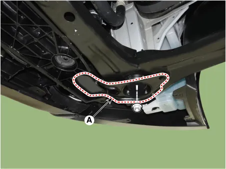
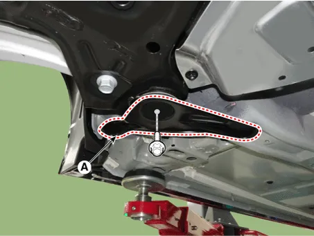
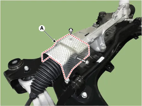
| 10. |
Remove the heat protector (A).
|
| 11. |
Remove the muffler rubber hanger (A).
|

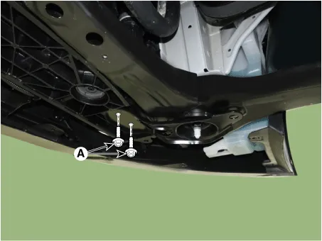
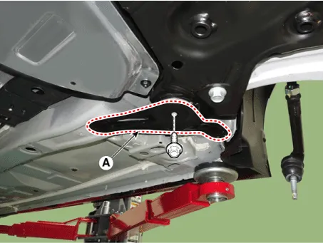
| 12. |
Remove the fasner (A).
|

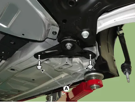
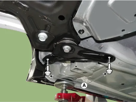
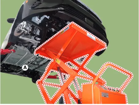
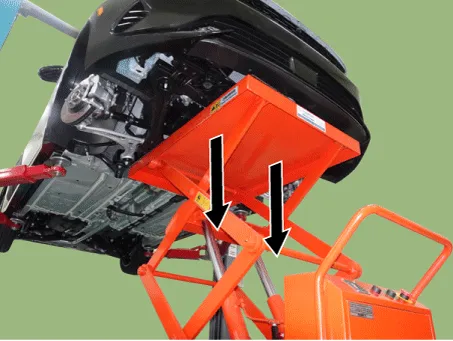
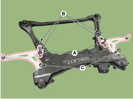
| 13. |
Remove the sub frame.
|


| 14. |
Loosen the bolts and remove the steering gear box heat protector (A).
|
| 15. |
Remove the steering gearbox (A) from the front sub frame by loosening the mounting bolts.
|
| 16. |
Loosen the mounting bolts and then remove the stabilizer bar (A).
|
| 17. |
Remove the lower arm (A).
|
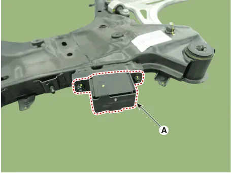
| 18. |
Remove the dynamic damper (A).
|
Repair procedures Removal 1. Disconnect the (-) battery terminal. 2. Remove the front wheel and tire.
Components and components location Components and Components Location 1. Trailing arm 2. Rear shock absorber 3. Rear suspension 4.
Other information:
Kia Optima DL3 2019-2026 Service and Repair Manual: Washer Motor
Repair procedures Inspection Washer Motor 1. With the washer motor connected to the reservoir tank, fill the reservoir tank with water. Before filling the reservoir tank with water, check the filter for foreign mat
Kia Optima DL3 2019-2026 Service and Repair Manual: Air Conditioning System
General safety information and caution Instructions (R-134a) When Handling Refrigerant 1. R-134a liquid refrigerant is highly volatile. A drop on the skin of your hand could result in localized frostbite. When handling the refrigerant, be sure to wear gloves.
Categories
- Manuals Home
- Kia Optima Owners Manual
- Kia Optima Service Manual
- Rear Brake Disc
- Floor Console Assembly
- Brake System
- New on site
- Most important about car
