Kia Optima DL3: Front Suspension System / Front Stabilizer Bar
Repair procedures
| Removal |
| 1. |
Disconnect the (-) battery terminal. |
| 2. |
Remove the front wheel and tire. (Refer to Tires/Wheels - "Wheel") |
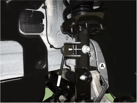
| 3. |
Disconnect the stabilizer link with the front strut assembly after loosening the nut (A).
|

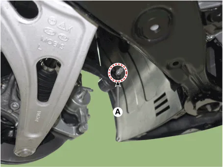
| 4. |
Loosen the nut (A) and disconnect the stabilizer bar link from the stabilizer bar.
|
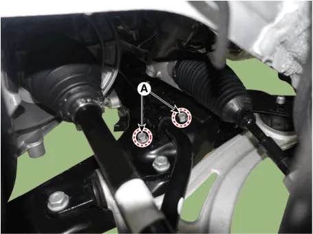
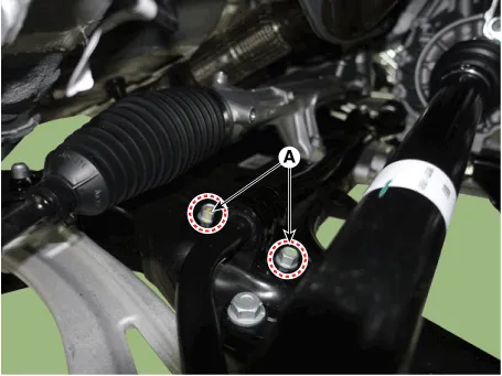
| 5. |
Loosen the bolt (A) and remove the stabilizer bar from the sub frame.
[LH]
[RH]
|
| Installation |
| 1. |
Install in the reverse order of removal. |
| 2. |
Check the alignment. (Refer to Suspension System - "Alingment") |
| Inspection |
| 1. |
Check the bushing for wear and deterioration. |
| 2. |
Check the front stabilizer bar for deformation. |
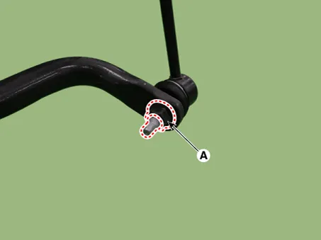
| 3. |
Check the front stabilizer link ball joint for damage. |
Repair procedures Removal 1. Disconnect the (-) battery terminal. 2. Remove the front wheel and tire.
Repair procedures Removal 1. Disconnect the (-) battery terminal. 2. Loosen the bolt (A) and remove the universal joint (B).
Other information:
Kia Optima DL3 2019-2026 Service and Repair Manual: Fog Lamp
Repair procedures Removal Front Fog Lamp 1. Disconnect the negative battery terminal. 2. Remove the front bumper assembly. (Refer to Body - "Front Bumper Assembly") 3.
Kia Optima DL3 2019-2026 Service and Repair Manual: Climate Control Air Filter
Description and operation Description The climate control air filter is located in the blower unit. It eliminates foreign materials and odor. The particle filter performs a role as an odor filter as well as a conventional dust filter to ensure comfortable interior environment.
Categories
- Manuals Home
- Kia Optima Owners Manual
- Kia Optima Service Manual
- Suspension System
- Engine Control / Fuel System
- Heating, Ventilation and Air Conditioning
- New on site
- Most important about car
