Kia Optima DL3: Surround View Monitor (SVM) / Surround View Monitor (SVM) ECU
Schematic diagrams
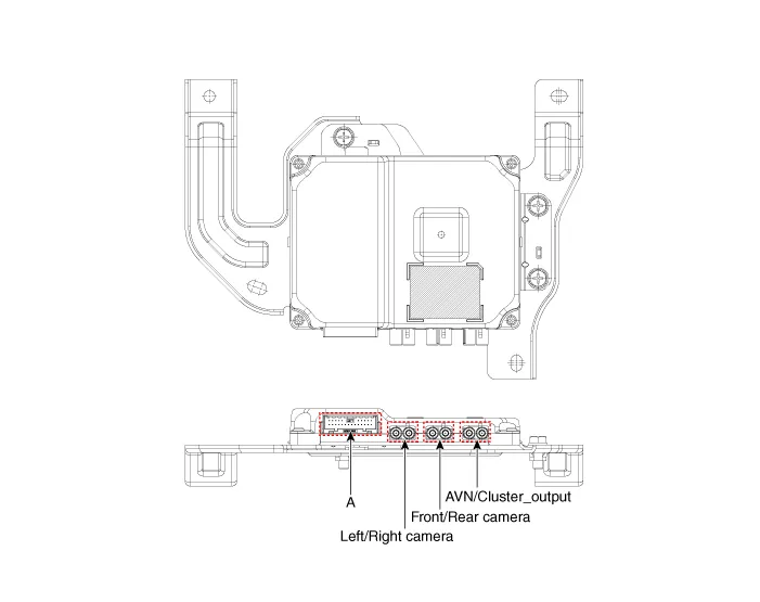
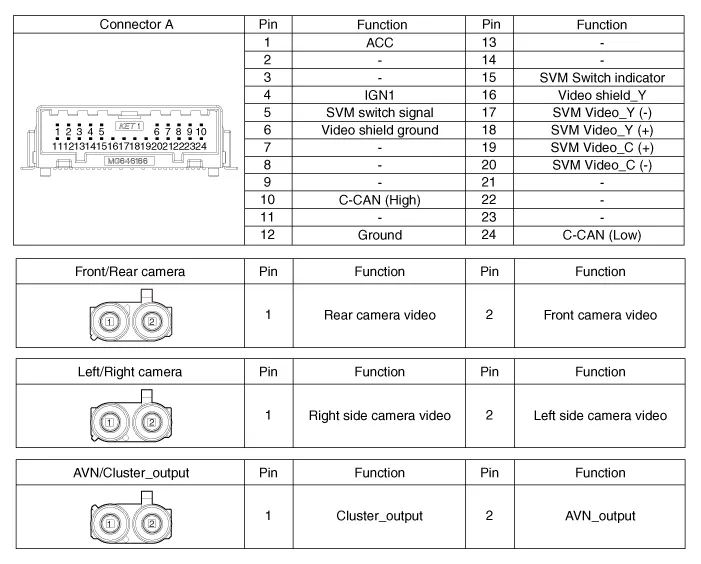
| Connector and Terminal function |
Repair procedures
| Removal |
| 1. |
Disconnect the negative (-) battery terminal. |
| 2. |
Remove the crash pad center panel. (Refer to Body - "Crash Pad Center Panel") |
| 3. |
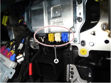
Disconnect the SVM ECU connectors (A).
|
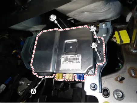
| 4. |
Remove the SVM ECU (A) after loosening the mounting bolts.
|
| Installation |
| 1. |
Install in the reverse order of removal. |
Components and components location Component Location Surround View Monitor (SVM) 1) SVM unit basically transmits data via C-CAN only.
Schematic diagrams Connector and Terminal function Front View Camera Side View Camera Rear View Camera Repair procedures Removal In case of bad quality or poor focus, be sure to check the camera lens surface condition and foreign materials.
Other information:
Kia Optima DL3 2019-2026 Service and Repair Manual: Ventilated and Heated Seat
Schematic diagrams Connector and Terminal Function Pin Function Connector A Connector B 1 Driver heater ground (-) Driver blower speed (+) 2 Passenger heater ground (-) - 3
Kia Optima DL3 2019-2026 Service and Repair Manual: Heating, Ventilation and Air Conditioning
Service data Service Data Air Conditioner ltem Specification Compressor Type 6SAS14 Oil type & Capacity ND-OIL 12 80 ± 10 cc (2.82 ± 0.
Categories
- Manuals Home
- Kia Optima Owners Manual
- Kia Optima Service Manual
- Automatic Transaxle System
- Steering System
- Rear Brake Disc
- New on site
- Most important about car
