Kia Optima DL3: Engine Control System / Manifold Absolute Pressure Sensor (MAPS) & Intake Air Temperature Sensor (IATS)
Specifications
| Specification |
| Manifold Absolute Pressure Sensor (MAPS) |
|
Pressure |
Output Voltage (V) |
||
|
kPa |
kgf/cm² |
psi |
|
|
20 |
0.2 |
2.9 |
0.79 |
|
46.7 |
0.47 |
6.77 |
1.84 |
|
106.7 |
1.03 |
14.7 |
4.2 |
| Intake Air Temperature Sensor (IATS) |
|
Temperature |
Resistance (kΩ) |
|
|
°C |
°F |
|
|
-40 |
-40 |
40.93 - 48.35 |
|
-20 |
-4 |
13.89 - 16.03 |
|
0 |
32 |
5.38 - 6.09 |
|
10 |
50 |
3.48 - 3.90 |
|
20 |
68 |
2.31 - 2.57 |
|
40 |
104 |
1.08 - 1.21 |
|
50 |
122 |
0.76 - 0.85 |
|
60 |
140 |
0.54 - 0.62 |
|
80 |
176 |
0.29 - 0.34 |
Description and operation
| Description |
| Manifold Absolute Pressure Sensor (MAPS) |
| • |
Installed on the surge tank, Manifold Absolute Pressure Sensor (MAPS) is a speed-density type sensor that senses absolute pressure of the surge tank and transfers the analog signal proportional to the pressure to the ECM. By using this signal, the ECM calculates the intake air amount and engine speed. |
| • |
The MAPS consists of a piezo-electric element and a hybrid IC amplifying the element output signal. This element, a silicon diaphragm type, features pressure sensitive variable resistor effect of semi-conductor. |
| • |
Due to 100% vacuum status and manifold pressure applied to both sides of the sensor, this sensor can output analog signal by using the silicon variation proportional to pressure change. |
| Intake Air Temperature Sensor (IATS) |
| • |
Intake Air Temperature Sensor (IATS) is included inside Manifold Absolute Pressure Sensor and detects the intake air temperature. |
| • |
To calculate precise air quantity, correction of the air temperature is needed because air density varies according to the temperature. So the ECM uses not only MAPS signal but also IATS signal. |
| • |
This sensor has a Negative Temperature Coefficient (NTC) and its resistance is in inverse proportion to the temperature. |

Components and components location
| Components Location |

| 1. Manifold Absolute Pressure
Sensor & Intake Air Temperature Sensor (MAPS & IATS) |
Schematic diagrams
| Circuit Diagram |

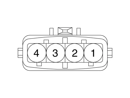
Harness Connector
Repair procedures
| Inspection |
| 1. |
The engine control system can be more quickly diagnosed for troubles by using the vehicle diagnostic system (KDS). (Refer to "DTC guide") KDS provides the following information.
|
| Components Inspection |
[MAPS]
| 1. |
Connect the KDS on the Data Link Connector (DLC). |
| 2. |
Measure the output voltage of the MAPS at idle and IG ON.
|
|||||||||||||||||||
[IATS]
| 1. |
Turn the ignition switch OFF. |
| 2. |
Disconnect the IATS connector. |
| 3. |
Measure resistance between the IATS terminals 3 and 4. |
| 4. |
Check that the resistance is within the specification.
|
||||||||||||||||||||||||||||||||
| Removal |
| 1. |
Disconnect the negative battery terminal. |
| 2. |
Remove the air duct (A).
|

| 3. |
After disconnecting the connector (A), remove the MAPS & IATS by loosening the bolt (B).
|

| Installation |
|

| 1. |
Install in the reverse order of removal. |
Specifications Specification Throttle angle (°) Output voltage (V) [Vref = 5.0V] TPS1 TPS2 0 0.
Specifications Specification Temperature Resistance (kΩ) °C °F 45 113 244.
Other information:
Kia Optima DL3 2019-2026 Service and Repair Manual: Condenser
Components and components location Components Location 1. Condenser Repair procedures Inspection 1. Check the condenser fins for clogging and damage. If clogged, clean them with water, and blow them with compressed air.
Kia Optima DL3 2019-2026 Service and Repair Manual: Receiver-Drier
Repair procedures Replacement 1. Remove the condenser. 2. Remove the cap (A) on the bottom of the condenser with a L wrench. Tightening torque : 9.81 - 14.71 N.
Categories
- Manuals Home
- Kia Optima Owners Manual
- Kia Optima Service Manual
- Body (Interior and Exterior)
- Cooling System
- Steering System
- New on site
- Most important about car
