Kia Optima DL3: Parking Distance Warning (PDW) / Parking Distance Warning (PDW) ON/OFF Switch
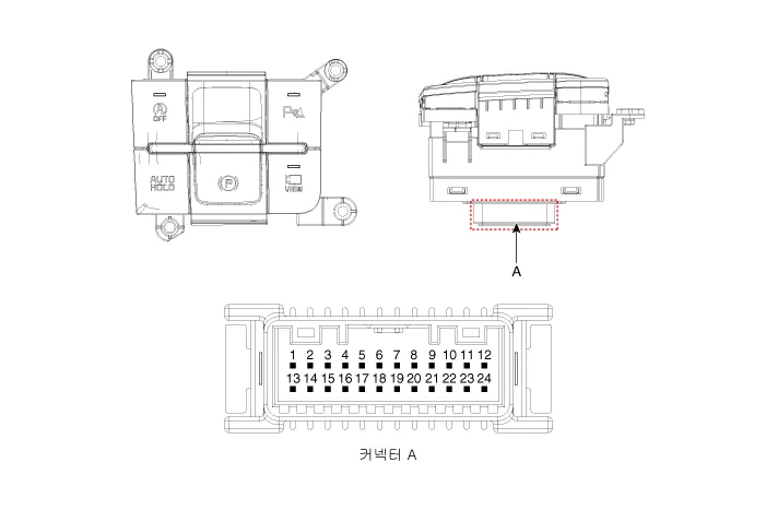
Schematic diagrams
| Connector and Terminal Function |
|
Pin |
Function |
Pin |
Function |
|
1 |
PAS mode switch |
13 |
SVM mode indicator |
|
2 |
PAS mode indicator |
14 |
SVM mode switch |
|
3 |
- |
15 |
- |
|
4 |
Detent |
16 |
Ground |
|
5 |
EPB switch1 |
17 |
EPB switch2 |
|
6 |
EPB switch3 |
18 |
EPB switch4 |
|
7 |
- |
19 |
- |
|
8 |
- |
20 |
IGN1 |
|
9 |
Battery (+) |
21 |
illumination (+) |
|
10 |
- |
22 |
- |
|
11 |
ISG mode indicator |
23 |
illumination (-) |
|
12 |
ISG mode switch |
24 |
Auto hold mode |
Repair procedures
| Inspection |
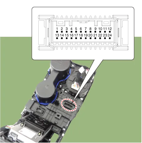
| 1. |
Remove the side crash pad switch. |
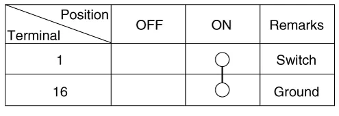
| 2. |
Operate the PDW on/off switch, then check for continuity between terminals.
|
| Removal |
|

| 1. |
Disconnect the negative battery terminal. |
| 2. |
Remove the console upper cover. (Refer to Body - "Floor Console Assembly") |
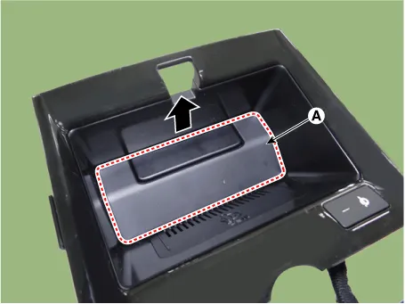
| 3. |
Remove the wireless power charger pad (A).
|
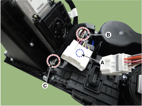
| 4. |
Disconnect the main connector fastener (A), consol switch connector (B) and wireless power charger indicator connector (C).
|
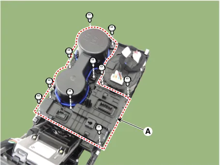
| 5. |
Remove the cup holder assembly (A) after loosening the mounting screws.
|
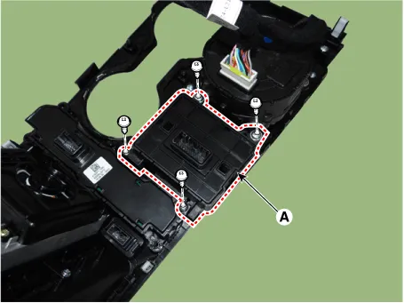
| 6. |
Remove the console switch (A) after loosening the mounting screws.
|
| Installation |
| 1. |
Install in the reverse order of removal. |
Schematic diagrams Circuit Diagram Repair procedures Removal Parking Distance Warning-Forward (PDW-F) Sensor 1.
Components and components location Component Location 1. Cluster (USM) 2. Parking collision-avoidance assist (PCA) Unit 3.
Other information:
Kia Optima DL3 2019-2026 Service and Repair Manual: Overhead Console Lamp
Schematic diagrams Connector and Terminal Function [A Type] Connector A Pin E xcept Russia Region Russia only Function Function 1 Battery (+) Battery (+)
Kia Optima DL3 2019-2026 Service and Repair Manual: Washer Motor
Repair procedures Inspection Washer Motor 1. With the washer motor connected to the reservoir tank, fill the reservoir tank with water. Before filling the reservoir tank with water, check the filter for foreign mat
Categories
- Manuals Home
- Kia Optima Owners Manual
- Kia Optima Service Manual
- Automatic Transaxle System
- Brake System
- Headlamps
- New on site
- Most important about car
