Kia Optima: Smart Key System / Smart Key Antenna
Repair procedures
| Removal |
Interior Antenna 1
| 1. |
Disconnect the negative battery terminal. |
| 2. |
Remove the surround view monitor (SVM) unit. (Refer to Advanced Driver Assistance System (ADAS) - "Surround View Monitor (SVM) Unit") |
| 3. |
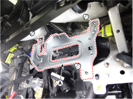
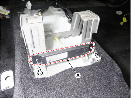
Remove the SVM bracket (A) by loosening the mounting nuts.
|
| 4. |
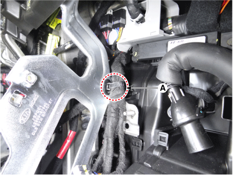
Remove the fixing clip (A) from the SVM bracket.
|
| 5. |
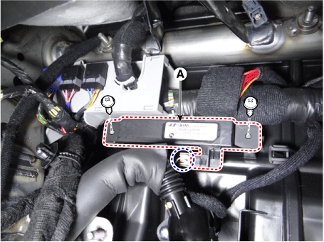
Remove the interior antenna 1 (A) by loosening the screws after disconnecting the connector.
|
Interior Antenna 2
| 1. |
Disconnect the negative battery terminal. |
| 2. |
Remove the floor console assembly. (Refer to Body - "Floor Console Assembly") |
| 3. |
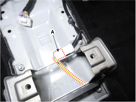
Disconnect the interior antenna 2 connector (A).
|
| 4. |
Remove the interior antenna 2 (A) by loosening the mounting screws.
|
Interior Antenna 3
| 1. |
Disconnect the negative battery terminal. |
| 2. |
Remove the rear transverse trim. (Refer to Body - "Rear Transverse Trim") |
| 3. |
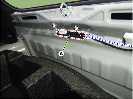
Remove the interior antenna 3 (A) by loosening the nuts after disconnecting the connector.
|
Exterior Bumper Antenna
| 1. |
Disconnect the negative battery terminal. |
| 2. |
Remove the rear bumper assembly. (Refer to Body - "Rear Bumper Assembly") |
| 3. |
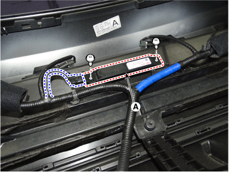
Remove the exterior bumper antenna (A) by loosening the screws after disconnecting the connector.
|
Front Antenna
| 1. |
Disconnect the negative battery terminal. |
| 2. |
Remove the front bumper assembly. (Refer to Body - "Front Bumper Assembly") |
| 3. |
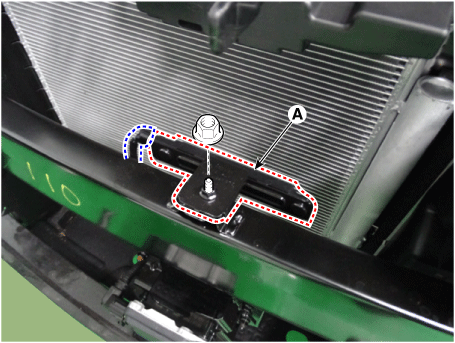
Remove the front antenna (A) by loosening the nut after disconnecting the connector.
|
Front Door Antenna
| 1. |
Disconnect the negative battery terminal. |
| 2. |
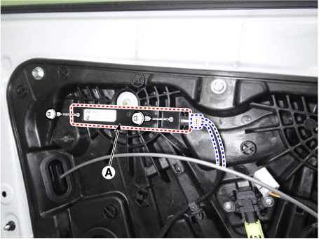
Remove the front door trim. (Refer to Body - "Front Door Trim") |
| 3. |
Remove the front door antenna (A) by loosening the screws after disconnecting the connector.
|
| Installation |
| 1. |
Install in the reverse of the removal. |
| Inspection |
| 1. |
Inspect the antenna by using the KDS. (Refer to Smart Key System - "Smart Key Diagnostic") |
 Smart Key Unit
Schematic diagrams
Connector and Terminal Function
Pin
Function
Connector A
Connector B
Connector C
Con ...
 Smart Key Diagnostic
Repair procedures
Inspection
1.
In the body electrical system, failure can be quickly diagnosed by using
the vehicle diagnostic system (KDS).
The diagnostic system ...
Other information:
Kia Optima DL3 2019-2025 Service and Repair Manual: Hood Assembly
Components and components location Component Location 1. Hood assembly Repair procedures Replacement When removing the fender, wrap protective tape around a screwdriver or ...
Kia Optima DL3 2019-2025 Service and Repair Manual: CVVT & Camshaft
Components and components location Components 1. Camshaft bearing cap 2. Camshaft front bearing cap 3. Exhaust camshaft 4. Intake camshaft 5. Exhaust CVVT assembly 6. Intake CVVT assembly Description and operation Description ...

