Kia Optima DL3: Motor Driven Power Steering / Steering Gear Box
Components and components location
| Components |
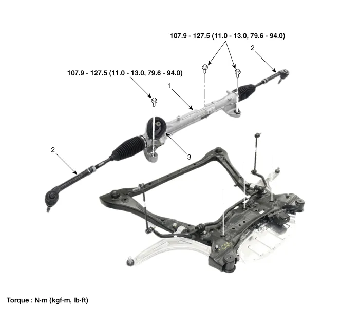
| 1. Steering
gear box 2. STie rod end |
3. Dust
cap |
Repair procedures
| Removal |
| 1. |
Align the steering wheel so that the front wheels to facing straight ahead.emove the front wheel and tire.
|

| 2. |
Turn the ignition OFF and disconnect the negative (-) battery terminal. |
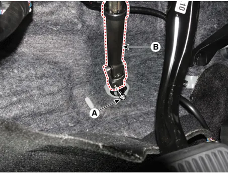
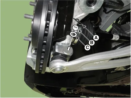
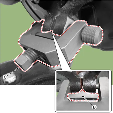
| 3. |
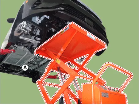
Loosen the bolt (A) and remove the universal joint (B).
|
| 4. |
Remove the front wheel and tire. (Refer to Tires/Wheels - "Wheel") |
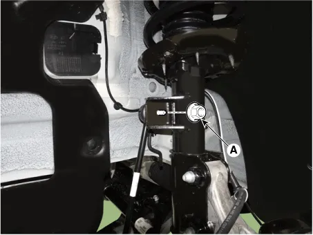
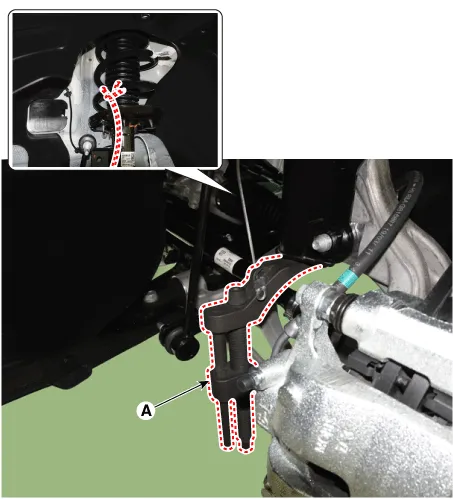
| 5. |
Disconnect the stabilizer link with the front strut assembly after loosening the nut (A).
|
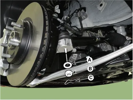
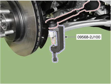
| 6. |
Disconnect the tie rod end ball joint from the knuckle by using the SST (09568-2J100).
|
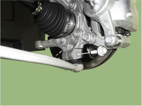
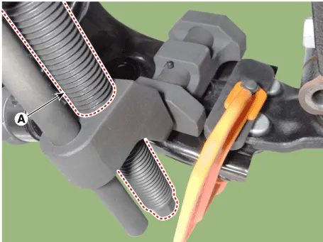
| 7. |
Loosen the lower arm mounting nut (A).
|
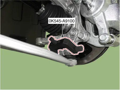
| 8. |
Disconnect lower arm ball joint from the knuckle by using the SST (0K545-A9100).
|
| 9. |
Remove the engine room under cover. G 2.0 NU MPI (Refer to Engine Mechanical System - "Engine Room Under Cover") G 2.5 GDI THETA II (Refer to Engine Mechanical System - "Engine Room Under Cover") |
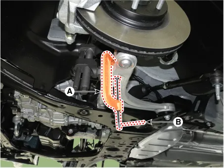
| 10. |
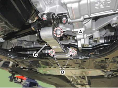
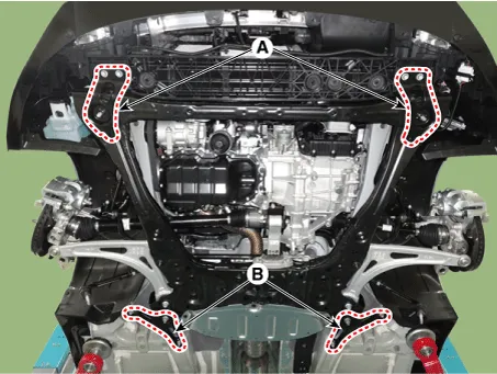
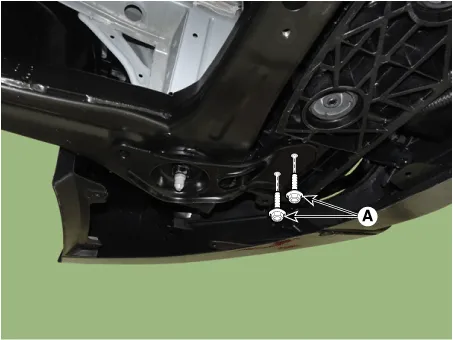
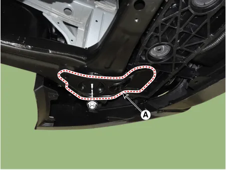
Separate the roll rod bracket (C) after loosening the bolts (A), (B).
|
| 11. |
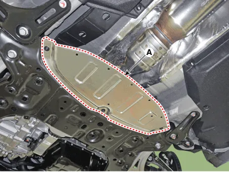
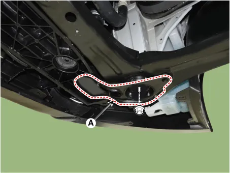
Remove the heat protector (A).
|
| 12. |
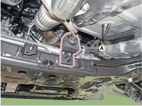
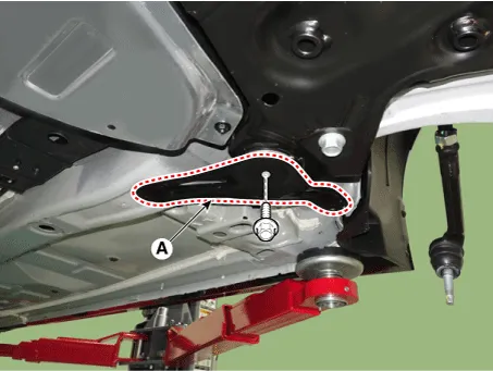
Remove the muffler rubber hanger (A).
|
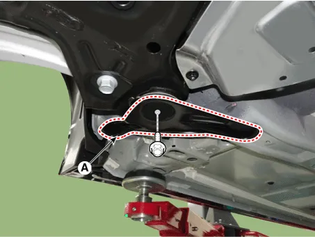
| 13. |
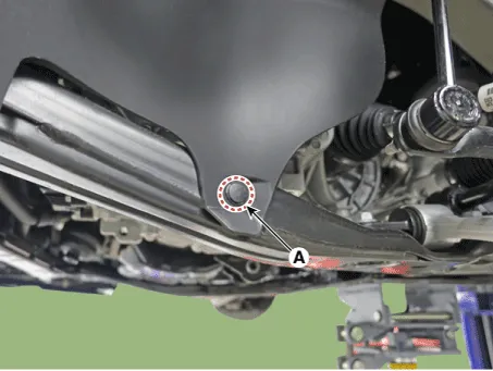
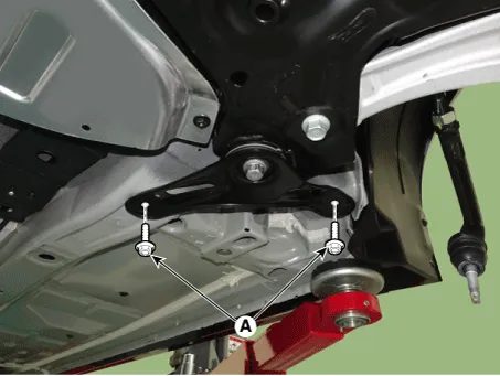
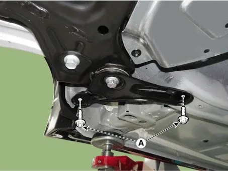
Remove the fasner (A).
|
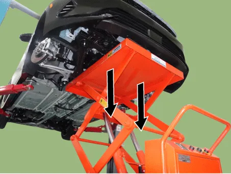
| 14. |
Remove the sub frame.
|


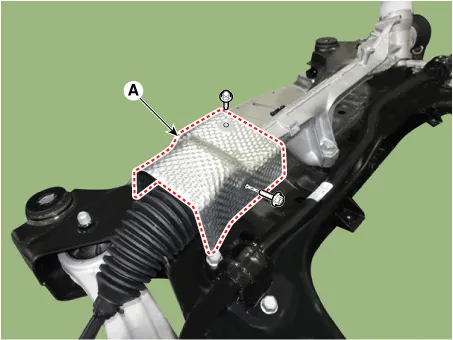
| 15. |
Remove the steering gear box heat protector (A) after loosening the mounting bolts
|
| 16. |
Remove the steering gear box (A) after loosening the mounting bolts
|

| Replacement |
|
| [Interchangeable parts] |
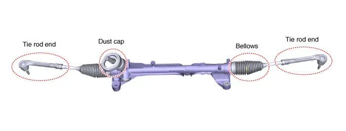
Tie rod end
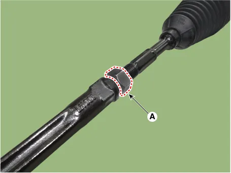
| 1. |
Loosen the tie rod end lock nut (A).
|

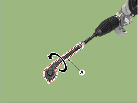
| 2. |
Remove the tie rod end (A) by loosening it in the counterclockwise.
|
| 3. |
Replace the tie rod end with a new one. |
| 4. |
Check the alignment. (Refer to Suspension System - "Alingment") |
Bellows
| 1. |
Remove the tie rod end. (Refer to Replacement - "Tie rod end") |
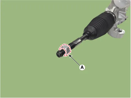
| 2. |
Remove the tie rod end lock nut (A).
|
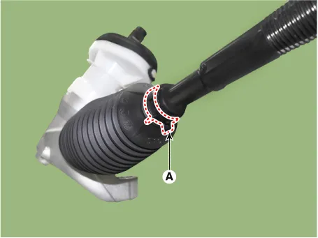
| 3. |
Remove the bellows clamp (A).
|
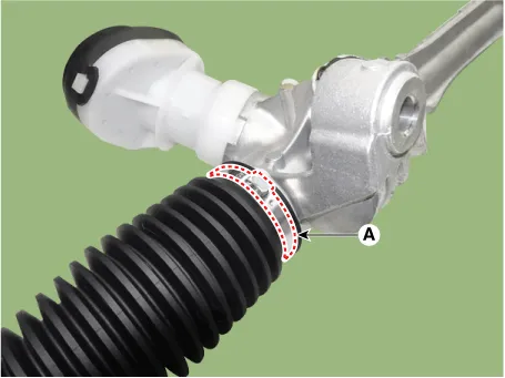
| 4. |
Remove the bellows band (A).
|
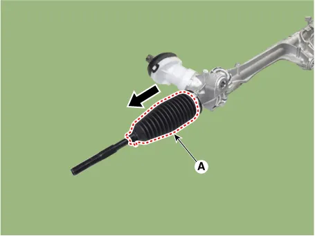
| 5. |
Remove the bellows (A) to the arrow direction.
|
| 6. |
Replace the bellows with a new one. |
| 7. |
Check the alignment. (Refer to Suspension System - "Alingment") |
Dust cap
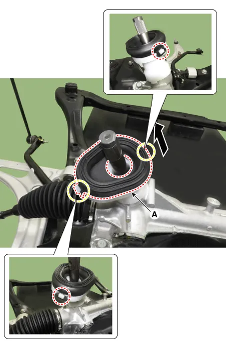
| 1. |
Remove the dust cap cover (A).
|
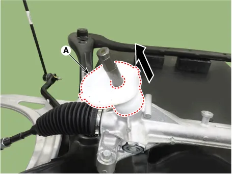
| 2. |
Remove the dust cap (A).
|
| 3. |
Replace the tie rod end with a new one.
|

| 4. |
Check the alignment. (Refer to Suspension System - "Alingment") |
| Installation |
Install the component to the specified torque. |
| 1. |
Install in the reverse order of removal. |
| 2. |
Perform the "EPS Type Recognition" by KDS. (Refer to MDPS System - "Diagnosis with KDS") |
| 3. |
Perform the "SAS Calibration" by KDS. (Refer to MDPS System - "Diagnosis with KDS") |
| 4. |
Check the alignment. (Refer to Suspension System - "Alingment") |
Repair procedures Removal 1. Align the steering wheel so that the front wheels to facing straight ahead. If the steering wheel and the front tires does not synchronize to their centers together, open circuit on the clock spring cable may occur due to change the steering wheel turning.
General information General The supplemental restraint system (SRS) is designed to supplement the seat belt to help reduce the risk or severity of injury to the driver and passenger by activating and deploying the driver, passenger, side airbag and seat belt pretensioner in certain frontal or side collisions.
Other information:
Kia Optima DL3 2019-2026 Service and Repair Manual: Personal Lamp
Repair procedures Removal When removing with a flat-tip screwdriver or remover, wrap protective tape around the tools to prevent damage to components. 1.
Kia Optima DL3 2019-2026 Service and Repair Manual: Lumbar Support System
Repair procedures Inspection 1. Remove the front seat back. (Refer to Body - "Front Seat Back Cover") 2. Disconnect the connector (A). 3. When the battery power is supplied to the motor connector, check the motor for smooth operation.
Categories
- Manuals Home
- Kia Optima Owners Manual
- Kia Optima Service Manual
- Charging System
- Headlamps
- Engine Mechanical System
- New on site
- Most important about car
