Kia Optima DL3: Charging System / Wireless Power Charger (WPC)
Specifications
| Specifications |
|
Items |
Specification |
|
Operating voltage |
DC 9 - 16 V |
|
Operating temperature |
-22 to 167 °F (-30 to +75 °C) |
|
Dark current |
MAX. 1 mA |
|
Output power |
7 - 10 W |
|
Output frequency |
115 kHz (iPhone : 127.7 kHz) |
Description and operation
| Description |
Wireless Power Charger System
During IG ON, battery voltage is supplied to the wireless power charger system to transmit an output of 5 W to mobile phone.
Mobile phones certified with the wireless charging standard WPC (Qi 1.2.4) or equipped with an exclusive wireless charging case can be used.
Wireless Power Charging System Flow Chart
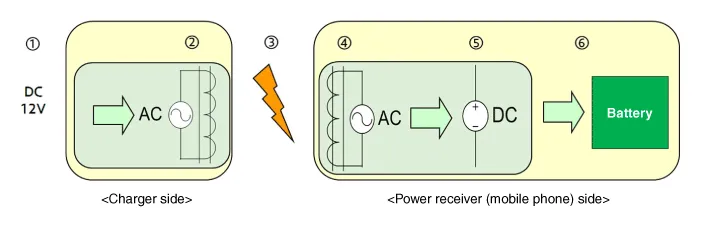
| 1. |
Supply vehicle power. |
| 2. |
Convert to AC. Generate electromagnetic field in 1st coil. |
| 3. |
Generate induced current in power receiver from electromagnetic induction. |
| 4. |
Generate AC in 2nd coil. |
| 5. |
Convert to DC. |
| 6. |
Charge battery. |
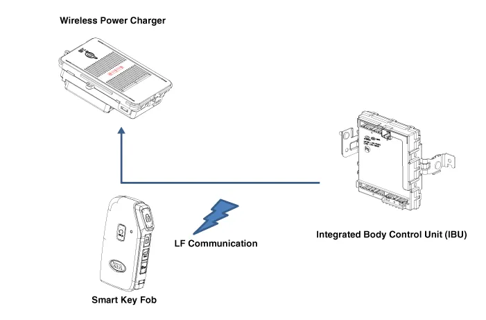
System Configuration Diagram
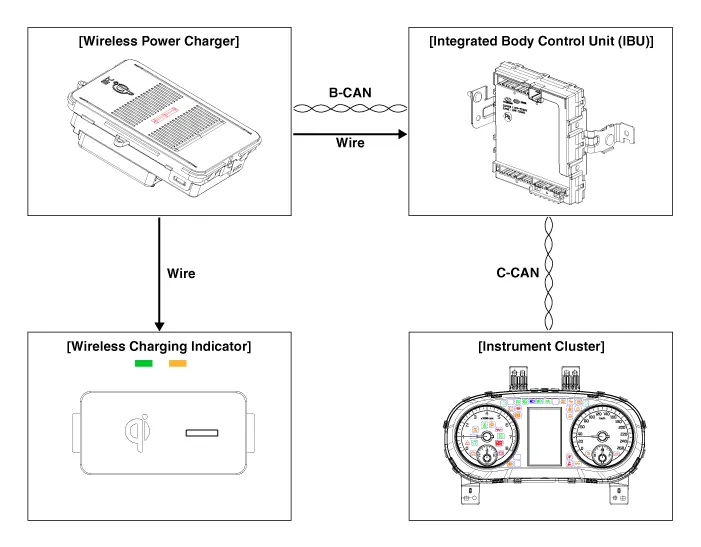
| 1. |
Instrument cluster : Alerts about contact with mobile phone. |
| 2. |
Wireless charging indicator : Displays the charging status. |
| 3. |
Wireless power charger (WPC) : Negligence of mobile phone, foeign object detection (FOD) decision. |
| 4. |
Integrated body control unit (IBU) : Stops charging during the activation of Low Frequency (LF). |
Wireless Power Charger system Major Functions
| 1. |
Charging Function
|
| 2. |
Mobile phone neglect alert function
|
| 3. |
Overheating prevention
|

| 4. |
Foreign matter detection
|

| 5. |
IBU unit low frequency (LF) interference prevention This function prevents interference between the wireless charging frequency and smart key unit frequency band.
|
| 6. |
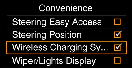
Turn the wireless charging function ON/OFF with USM.
※ Tailgate applies to RV vehicle models. |
Wireless Power Charger (WPC) System Protection
|
Item |
Condition |
Status |
|
Protects against low/high voltage |
Protects and stops charging under 8.5 V and over 16.5 V |
LED OFF (Stops operation) |
|
Charges between 9 - 16 volts |
||
|
Protects against reverse voltage |
Protects and stops charging in case of reverse voltage |
LED OFF (Stops operation) |
|
Protects against overcurrent |
Protects and stops charging in case of detecting 4 amps |
Amber LED blinks |
|
Protects against overheating |
Protects and stops charging in case of detecting 158°F (70°C) by internal
temperature sensor of wireless charging module |
Amber LED blinks |
|
Resumes under 149°F (65°C) |
||
|
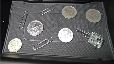
Foreign matter (Coins, clips, precious metals, etc.) |
Protects and stops charging in case of detecting foreign matter (overheating
prevention) |
Amber LED blinks |
|
Prevents frequency interference |
Protects and stops charging by activating IBU in case door or trunk is open
|
LED OFF (Stops operation) |
|
Resumes in 3.5 seconds after all doors and trunk are closed and IBU operation
is completed |
||
|
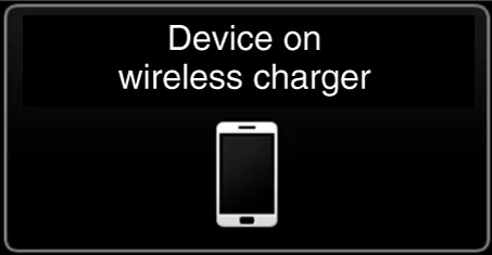
Alert for contact with mobile phone |
In case of smart phone on the charging pad when opening the door after ignition
OFF |
Displays warning message on the instrument panel (for about 4 seconds)
|
※ Tailgate applies to RV vehicle models.
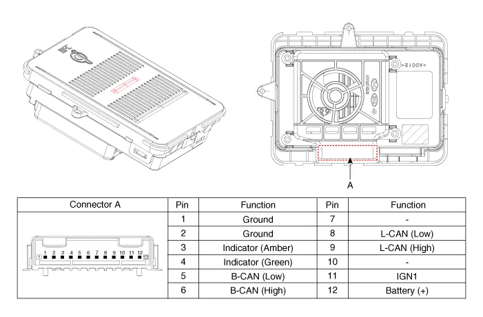
Schematic diagrams
| Connector and Terminal function |
Repair procedures
| Inspection |
| 1. |
The body electrical system can be more quickly diagnosed for troubles by using the vehicle diagnostic system (KDS). KDS provides the following information.
|
| 2. |
To diagnose the vehicle by using the diagnostic equipment, select "vehicle model" and "wireless power charger system" to be inspected. |
| 3. |
To inquire the current status of input/output values, select the "Sensor Data" menu The input/output values of the sensors corresponding to the selected module can be checked. |
| 4. |
To perform forced operation of the selected module input, select "Actuation Test". |
| 5. |
To inquire the cause of trouble for each module by self diagnosis, select 'Diagnostic Trouble Code'. |
| Removal |
Wireless Power Charger (WPC)
| 1. |
Disconnect the negative battery terminal. |
| 2. |
Remove the console upper cover. (Refer to Body - "Floor Console Assembly") |
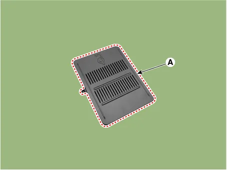
| 3. |
Remove the wireless power charger pad (A).
|

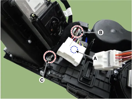
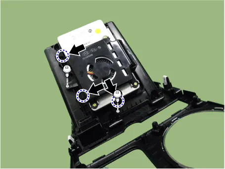
| 4. |
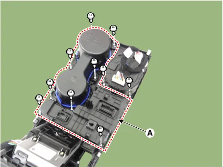
Disconnect the all connectors from the console floor switch complete. (A) : Main connector fixing fastener (B) : Console floor switch complete connector (C) : Wireless charging indicator connector
|
| 5. |
Remove the console cup holder assembly (A) by loosening the mounting screws.
|
| 6. |
Remove the EPB switch assembly (A) by loosening the mounting screws.
|
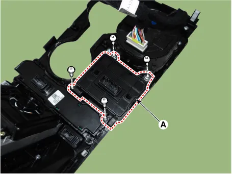
| 7. |
Remove the console floor switch complete (A).
|
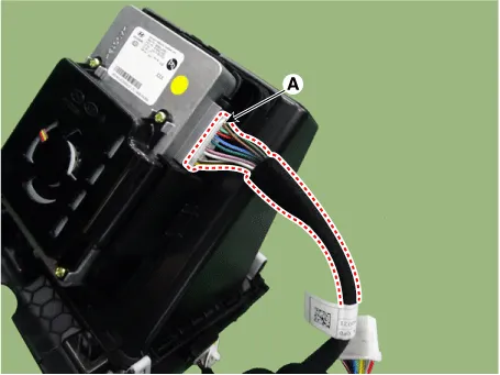
| 8. |
Remove the wireless power charger connector (A).
|
| 9. |
Loosen the wireless power charger mounting screws. |
| 10. |
Remove the wireless power charger (A) by pushing the hooks in the direction of arrow.
|
Wireless Power Charger (WPC) Pan
| 1. |
Disconnect the negative battery terminal. |
| 2. |
Remove the console upper cover. (Refer to Body - "Floor Console Assembly") |
| 3. |
Remove the wireless power charger pad (A).
|
| 4. |
Disconnect the all connectors from the console floor switch complete. (A) : Main connector fixing fastener (B) : Console floor switch complete connector (C) : Wireless charging indicator connector
|
| 5. |
Remove the console cup holder assembly (A) by loosening the mounting screws.
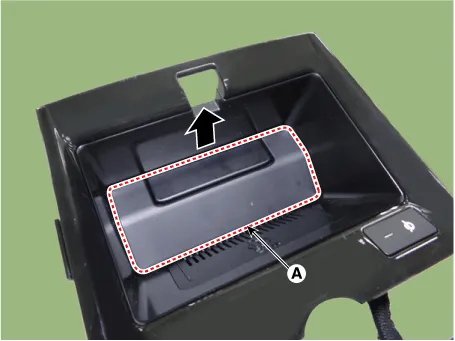
|
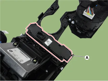
| 6. |
Remove the wireless power charger pan cover (A) by loosening the mounting screws.
|

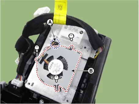
| 7. |
Disconnect the wireless power charger pan connector (A). |
| 8. |
Remove the wireless power charger pan (B) by loosening the mounting screws.
|
| Installation |
| 1. |
Install in the reverse order of removal. |
Schematic diagrams Connector and Terminal function Repair procedures Removal [Floor Console Tray] 1. Disconnect the negative battery terminal.
Schematic diagrams Connector and Terminal function Pin Function 1 Ground 2 LED charging lamp (Green) 3 LED charging lamp (Amber) 4 - 5 Illumination (-) 6 Illumination (+) Repair procedures Removal 1.
Other information:
Kia Optima DL3 2019-2026 Service and Repair Manual: Integrated Memory Seat (IMS) Unit
Specifications Specifications Item Specifications Rated voltage DC 12 V Operating voltage DC 9 - 16 V Operating temperature range -22 to 167°F (-30 to 75°C) Dark current Max.
Kia Optima DL3 2019-2026 Service and Repair Manual: Hazard Lamp Switch
Schematic diagrams Connector and Terminal Function Repair procedures Removal 1. Disconnect the negative battery terminal. 2. Remove the crash pad garnish [RH]. (Refer to Body - "Crash Pad Garnish") 3.
Categories
- Manuals Home
- Kia Optima Owners Manual
- Kia Optima Service Manual
- Front Axle Assembly
- Lift And Support Points
- Suspension System
- New on site
- Most important about car
