Kia Optima DL3: Charging System / Battery
Description and operation
| 1. |
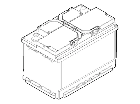
The CMF(Closed Maintenance Free) battery is, as the name implies, totally
maintenance free and has no removable battery cell caps.
|
| 2. |
The CMF(Closed Maintenance Free) battery does not require water replenishment
for the repair.
|
| 3. |
The battery is completely sealed, except for small vent holes in the
cover.
|
| • |
After disconnecting then reconnecting the battery negative cable,
reset some parts that require the reset procedures.
(Refer to Body Electrical System - "General Information")
|
|
Specifications
▶CMF68L-DIN
Item
|
Specification
|
Model typeModel type
|
CMF68L-DIN
|
Capacity [20HR/5HR] (AH)
|
68 / 54
|
Cold Cranking Amperage (A)
|
600 (SAE / EN)
|
Reserve Capacity (Min)
|
113
|
| • |
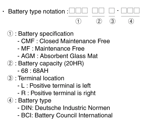
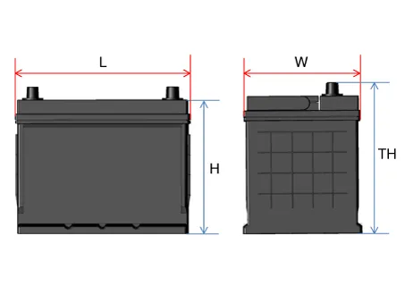
Model type description
|
| • |
Cold Cranking Ampere (CCA): Cold Cranking Amps is a rating used
in the battery industry to define a battery's ability to start an
engine in cold temperatures.
|
| – |
The rating is the number of amps a new, fully charged battery
can deliver at -18 °C(-0.4 °F) for 30 seconds, while maintaining
a voltage of at least 7.2 volts for a 12 volt battery.
|
| – |
The higher the CCA rating, the greater the starting power of
the battery.
|
| • |
RESERVE CAPACITY (RC) : Reserve Capacity is a battery industry
rating, defining a battery's ability to power a vehicle with an
inoperative alternator or fan belt.
|
| – |
The rating is the number of minutes a battery at 26.7 °C(80 °F)
can be discharged at 25 amps and maintain a voltage of 10.5 volts
for a 12 volt battery.
|
| – |
The higher the reserve rating, the longer your vehicle can operate
should your alternator or fan belt fail.
|
|
|
BCI Type
Capacity
(5 hr / 20 hr)
|
Length
|
Width
|
Height
|
Total Height
|
L (mm)
|
W (mm)
|
H (mm)
|
TH (mm)
|
28/35
|
188 - 192
|
126 - 130
|
198 - 202
|
218 - 222
|
32/40
|
194 - 198
|
133 - 137
|
199 - 203
|
223 - 227
|
36/45
|
203 - 207
|
173 - 177
|
200 - 204
|
221 - 225
|
44/55
|
213 - 217
|
173 - 177
|
198 - 202
|
218 - 222
|
48/60
|
228 - 232
|
173 - 177
|
200 - 204
|
221 - 225
|
54/68
|
258 - 262
|
173 - 177
|
198 - 202
|
220 - 224
|
56/70
|
258 - 262
|
173 - 177
|
198 - 202
|
223 - 227
|
64/80
|
274 - 278
|
170 - 174
|
198 - 202
|
221 - 225
|
70/88
|
349 - 353
|
172 - 176
|
186 - 200
|
183 - 187
|
72/90
|
300 - 304
|
170 - 174
|
200 - 204
|
221 - 225
|
76/95
|
294 - 298
|
172 - 176
|
198 - 202
|
220 - 224
|
80/100
|
326 - 330
|
170 - 174
|
203 - 207
|
225 - 229
|
DIN Type
Capacity
(5 hr / 20 hr)
|
Length
|
Width
|
Height
|
Total Height
|
L (mm)
|
W (mm)
|
H (mm)
|
TH (mm)
|
36/45
|
205 - 207
|
173 - 175
|
164 - 168
|
188 - 190
|
48/60
|
240 - 242
|
173 - 175
|
164 - 168
|
188 - 190
|
54/68
|
276 - 278
|
173 - 175
|
164 - 168
|
188 - 190
|
64/80
|
313 - 315
|
173 - 175
|
164 - 168
|
188 - 190
|
72/90
|
351 - 353
|
173 - 175
|
164 - 168
|
188 - 190
|
80/100
|
351 - 353
|
173 - 175
|
164 - 168
|
188 - 190
|
88/110
|
392 - 394
|
173 - 175
|
164 - 168
|
188 - 190
|
AGM DIN Type
Capacity
(5 hr / 20 hr)
|
Length
|
Width
|
Height
|
Total Height
|
L (mm)
|
W (mm)
|
H (mm)
|
TH (mm)
|
40/50
|
205 - 207
|
173 - 175
|
164 - 168
|
188 - 190
|
48/60
|
227 - 229
|
173 - 175
|
164 - 168
|
188 - 190
|
56/70
|
276 - 278
|
173 - 175
|
164 - 168
|
188 - 190
|
64/80
|
312 - 314
|
173 - 175
|
164 - 168
|
188 - 190
|
72/90
|
351 - 353
|
173 - 175
|
164 - 168
|
188 - 190
|
84/105
|
392 - 394
|
173 - 175
|
164 - 168
|
188 - 190
|
|
Repair procedures
Battery
| 1. |
Turn the ignition switch OFF.
|
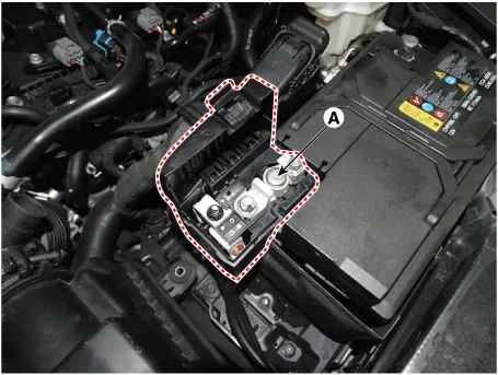
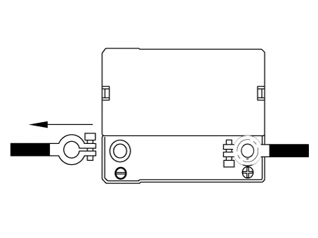
| 2. |
Disconnect the battery (-) terminal (A).
|
Tightening torque :
4.0 - 6.0 N.m (0.4 - 0.6 kgf.m, 3.0 - 4.4 lb-ft)
|
|
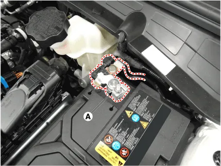
| 3. |
Remove the battery (+) terminal (A).
|
Tightening torque :
7.8 - 9.8 N.m (0.8 - 1.0 kgf.m, 5.8 - 7.2 lb-ft)
|
|
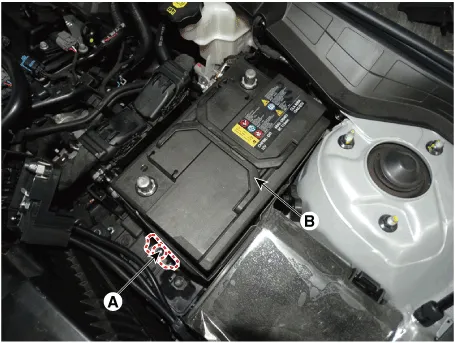
| 4. |
Remove the battery mouting bracket (A).
|
| 5. |
Remove the battery insulation pad after removing the battery (B).
|
Tightening torque :
19.6 - 29.4 N.m (1.9 - 3.0 kgf.m, 13.7 - 30.4 Ib-ft)
|
|
Battery tray
| 1. |
Remove the battery.
(Refer to "Removal")
|
| 2. |
Remove the air cleaner assembly.
(Refer to Engine Mechanical System - "Air Cleaner")
|
| 3. |
Remove the ECM.
(Refer to Engine Control / Fuel System - "Engine Control Module (ECM)")
|
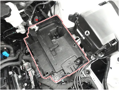
| 4. |
Remove the battery tray (A) after loosening the nuts.
|
Tightening torque :
7.8 - 9.8 N.m (0.8 - 1.0 kgf.m, 5.8 - 7.2 lb-ft)
|
|
| 1. |
Install in the reverse order of removal.
| •
|
When installing the battery, fix the mounting bracket
on the tray correctly.
|
|
| •
|
After disconnecting then reconnecting the battery negative
cable, reset some parts that require the reset procedures.
(Refer to Body Electrical System - "General Information")
|
|
|
Battery Voltage and
Status
Check the battery voltage and status by using a battery tester.
Battery Terminal
| 1. |
Move back and forth to check if the battery terminals (A) are loose or
corroded. Clean any corroded terminals.
If the battery positive connection is loose, disconnect the ground (GND)
cable first before attempting to remove or tighten the positive connection
to prevent personal injury.
|
| 2. |
If the battery clamp on positive (+) battery terminal is not seated securely:
| (1) |
Turn ignition switch OFF and disconnect the negative (-) battery
terminal.
|
| (2) |
Tighten battery clamp (A) on positive (+) battery terminal.
|
Tightening torque :
7.8 - 9.8 N.m (0.8 - 1.0 kgf.m, 5.8 - 7.2 lb-ft)
|
|
|
| 3. |
If the battery clamp on negative (-) battery terminal is not seated securely:
| (1) |
Tighten battery clamp (A) on negative (-) battery terminal.
|
Tightening torque :
4.0 - 6.0 N·m (0.4 - 0.6 kgf·m, 3.0 - 4.4 lb·ft)
|
|
|
Battery Condition
Check the battery for damage or deformation. If severe damage, deformation or
leakage is found, replace the battery.
Vehicle parasitic current
inspection
[Using the Ammeter]
| 1. |
Turn the all electric devices OFF, and then turn the ignition switch
OFF.
|
| 2. |
Close all doors except the engine hood, and then lock all doors.
| (1) |
Disconnect the hood switch connector.
|
| (3) |
Close the doors or remove the door switches.
|
|
| 3. |
Wait a few minutes until the vehicle’s electrical systems go to sleep
mode.
| •
|
For an accurate measurement of a vehicle parasitic current,
all electrical systems should go to sleep mode. (It takes
at least one hour or at most one day.) However, an approximate
vehicle parasitic current can be measured after 10-20 minutes.
|
|
|
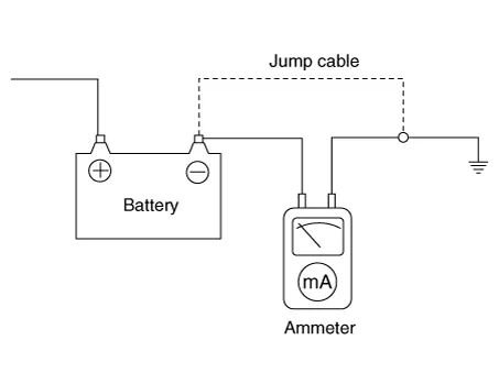
| 4. |
Connect an ammeter in series between the battery (-) terminal and the
ground cable, and then disconnect the clamp from the battery (-) terminal
slowly.
| •
|
Be careful that the lead wires of an ammeter do not come
off from the battery (-) terminal and the ground cable to
prevent the battery from being reset. In case the battery
is reset, connect the battery cable again, and then start
the engine or turn the ignition switch ON for more than
10 sec. Repeat the procedure from No. 1.
To prevent the battery from being reset during the inspection,
|
| 1) |
Connect a jump cable between the battery (-) terminal
and the ground cable.
|
| 2) |
Disconnect the ground cable from the battery (-) terminal.
|
| 3) |
Connect an ammeter between the battery (-) terminal and
the ground cable.
|
| 4) |
After disconnecting the jump cable, read the current
value of the ammeter.
|
|
|
| 5. |
Read the current value of the ammeter.
| • |
If the parasitic current is over the limit value, search for
abnormal circuit by removing a fuse one by one and checking the
parasitic current.
|
| • |
Reconnect the suspected parasitic currentdraw circuit fuse only
and search for suspectedunit by removing the component connected
with thecircuit one by one until the parasitic draw dropsbelow limit
value.
|
|
Limit value (after 10 - 20 min.) : Below 50 mA
|
|
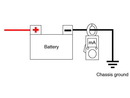
[Using the Clamp type Ammeter]
| 1. |
Turn the all electric devices OFF, and then turn the ignition switch
OFF.
|
| 2. |
Close all doors except the engine hood, and then lock all doors.
| (1) |
Disconnect the hood switch connector.
|
| (3) |
Close the doors or remove the door switches.
|
|
| 3. |
Wait a few minutes until the vehicle’s electrical systems go to sleep
mode.
| •
|
For an accurate measurement of a vehicle parasitic current,
all electrical systems should go to sleep mode. (It takes
at least one hour or at most one day.) However, an approximate
vehicle parasitic current can be measured after 10 - 20
minutes.
|
|
|
| 4. |
Install the clamp type ammerter on battery negative (-) terminal.
|
| 5. |
Read the current value of the ammeter.
| • |
If the parasitic current is over the limit value, search for
abnormal circuit by removing a fuse one by one and checking the
parasitic current.
|
| • |
Reconnect the suspected parasitic currentdraw circuit fuse only
and search for suspectedunit by removing the component connected
with thecircuit one by one until the parasitic draw dropsbelow limit
value.
|
|
Limit value (after 10 - 20 min.) : Below 50 mA
|
|
| 1. |
Make sure the ignition switch and all accessories are in the OFF position.
|
| 2. |
Disconnect the battery cables (negative first).
|
| 3. |
Remove the battery from the vehicle.
| •
|
Care should be taken in the event the battery case is
cracked or leaking, to protect your skin from the electrolyte.
Heavy rubber gloves (not the household type) should be
wore when removing the battery.
|
|
|
| 4. |
Inspect the battery tray for damage caused by the loss of electrolyte.
If acid damage is present, it will be necessary to clean the area with a
solution of clean warm water and baking soda. Scrub the area with a stiff
brush and wipe off with a cloth moistened with baking soda and water.
|
| 5. |
Clean the top of the battery with the same solution as described above.
|
| 6. |
Inspect the battery case and cover for cracks. If cracks are present,
the battery must be replaced.
|
| 7. |
Clean the battery posts with a suitable battery post tool.
|
| 8. |
Clean the inside surface of the terminal clamps with a suitable battery
cleaning tool. Replace damaged or frayed cables and broken terminal clamps.
|
| 9. |
Install the battery in the vehicle.
|
| 10. |
Connect the cable terminals to the battery post, making sure tops of
the terminals are flush with the tops of the posts .
|
| 11. |
Tighten the terminal nuts securely.
|
| 12. |
Coat all connections with light mineral grease after tightening.
| •
|
When batteries are being charged, an explosive gas forms
beneath the cover of each cell. Do not smoke near batteries
being charged or which have recently been charged. Do not
break live circuit at the terminals of batteries being charged.
A spark will occur when the circuit is broken. Keep open
flames away from battery.
|
|
|
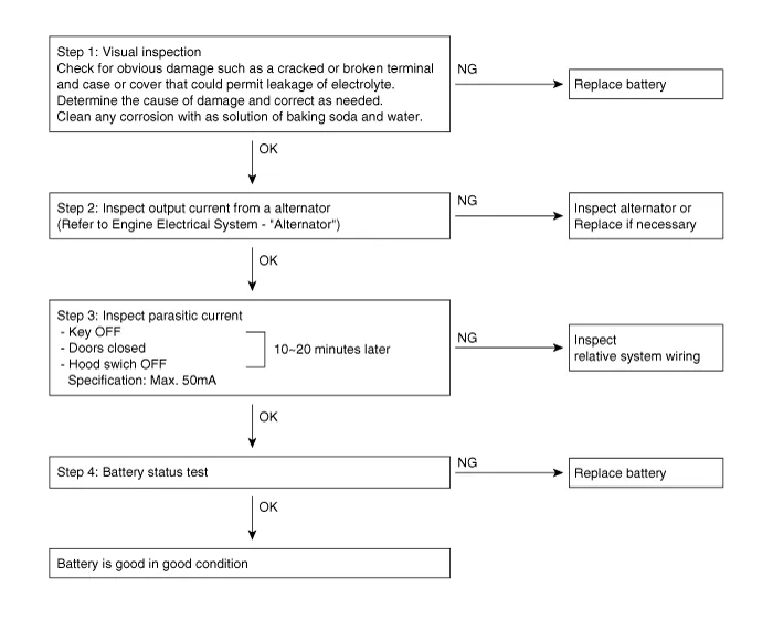
Troubleshooting
Description and operation
Description
The Alternator has eight built-in diodes, each rectifying AC current to DC current.
Therefore, DC current appears at alternator "B" terminal.
Description and operation
Description
Vehicles have many control units that use more electricity. These units control
their own system based on information from diverse sensors.
Other information:
Schematic diagrams
Connector and Terminal Function
Repair procedures
Removal
1.
Disconnect the negative battery terminal.
2.
Remove the crash pad lower panel.
(Refer to Body - "Crash Pad Lower Panel")
3.
Components and components location
Components Location
1. Suction & Liquid tube assembly
2. Discharge hose
Repair procedures
Replacement
1.
If the compressor is marginally operable, run the engine at idle speed,
and let the air conditioning work for a few minute


