Kia Optima DL3: Cylinder Head Assembly / CVVT & Camshaft
Components and components location
| Components |

| 1. Camshaft bearing cap 2. Camshaft front bearing cap 3. Exhaust camshaft |
4. Intake camshaft 5. Exhaust CVVT assembly 6. Intake CVVT assembly |
Description and operation
| Description |
Continuous Variable Valve Timing (CVVT) system advances or retards the valve timing of the intake and exhaust valve in accordance with the ECM control signal which is calculated by the engine speed and load.
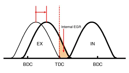
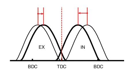
By controlling CVVT, the valve over-lap or under-lap occurs, which makes better fuel economy and reduces exhaust gases (NOx, HC) and improves engine performance through reduction of pumping loss, internal EGR effect, improvement of combustion stability, improvement of volumetric efficiency, and increase of expansion work.
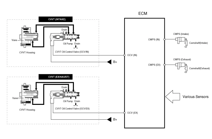
This system consist of
| – |
the CVVT Oil Control Valve (OCV) which supplies the engine oil to the cam phaser or runs out the engine oil from the cam phaser in accordance with the ECM PWM (Pulse With Modulation) control signal, |
| – |
the CVVT Oil Temperature Sensor (OTS) which measures the engine oil temperature, |
| – |
and the Cam Phaser which varies the cam phase by using the hydraulic force of the engine oil. |
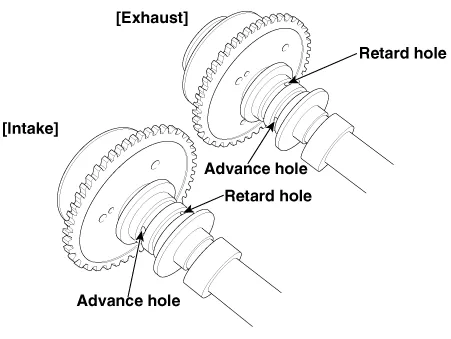
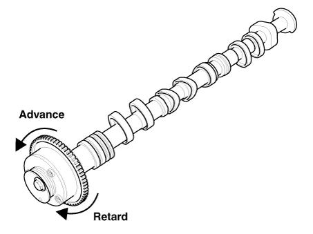
The engine oil getting out of the CVVT oil control valve varies the cam phase in the direction (Intake Advance/Exhaust Retard) or opposite direction (Intake Retard/Exhaust Advance) of the engine rotation by rotating the rotor connected with the camshaft inside the cam phaser.
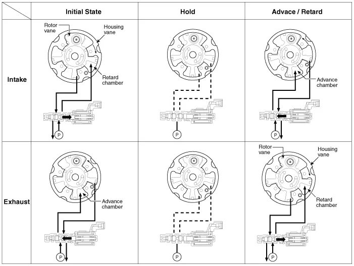
| Operation Principle |
The CVVT has the mechanism rotating the rotor vane with hydraulic force generated by the engine oil supplied to the advance or retard chamber in accordance with the CVVT oil control valve control.
| [CVVT System Mode] |

|
(1) Low Speed / Low Load |
(2) Part Load |
|
|
|
|
(3) Low Speed / High Load |
(4) High Speed / High Load |
|
|
|

|
Driving Condition |
Exhaust Valve |
Intake Valve |
||
|
Valve Timing |
Effect |
Valve Timing |
Effect |
|
|
(1) Low Speed /Low Load |
Completely Advance |
* Valve Under-lap * Improvement of combustion stability |
Completely Retard |
* Valve Under-lap * Improvement of combustion stability |
|
(2) Part Load |
Retard |
* Increase of expansion work * Reduction of pumping loss * Reduction of HC |
Retard |
* Reduction of pumping loss |
|
(3) Low Speed /High Load |
Retard |
* Increase of expansion work |
Advance |
* Prevention of intake back flow (Improvement of volumetric efficiency)
|
|
(4) High Speed /High Load |
Advance |
* Reduction of pumping loss |
Retard |
* Improvement of volumetric efficiency |
Repair procedures
| Removal |
|

|

Timing chain cover removal is not required for this procedure.
| 1. |
Remove the cylinder head cover. (Refer to Cylinder Head Assembly - “Cylinder Head Cover”) |
| 2. |
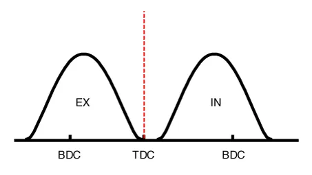
Set No.1 cylinder to TDC (Top dead center) on compression stroke.
|
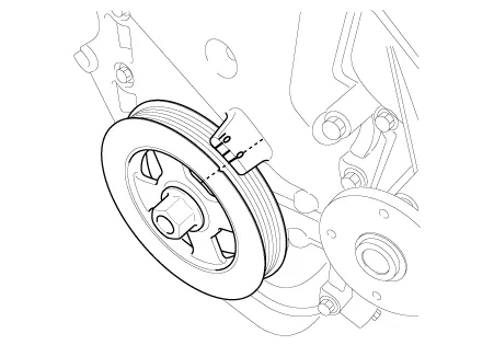
| 3. |
Remove the crankshaft damper pulley. (Refer to Drive Belt System - “Crankshaft Damper Pulley”) |
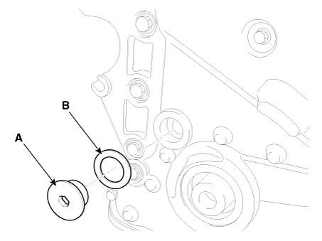
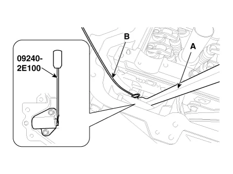
| 4. |
Remove the service plug bolt (A) with the gasket (B).
|
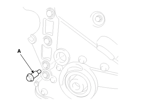
| 5. |
Remove the tensioner arm bolt (A).
|
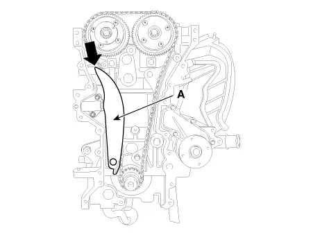
| 6. |
Push down the tensioner arm (A). [Timing Cover off For illustration Only]
|
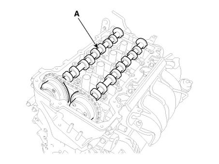
| 7. |
Remove the camshaft bearing caps.
|
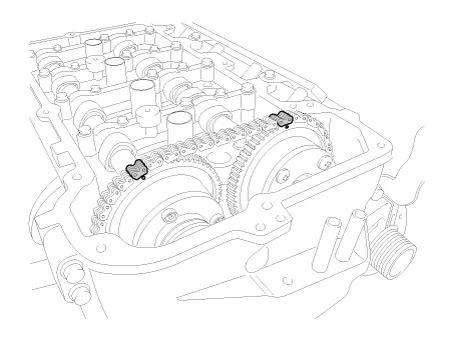
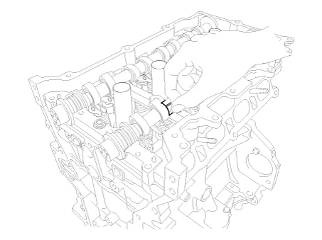
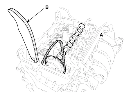
| 8. |
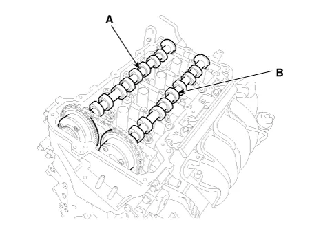
Remove the exhaust camshaft (A) first, then intake camshaft (B).
|
| 9. |
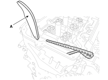
Remove the tensioner arm (A).
|
| 10. |
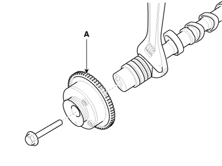
Remove the CVVT assembly (A) from the camshaft.
|
| Inspection |
Camshaft
| 1. |
Inspect the cam lobes. Using a micrometer, measure the cam lobe height. If the cam lobe height is less than specification, replace the camshaft.
|
| 2. |
Check the surface of the camshaft journal for wear. If the journal is worn excessively, replace the camshaft. |
| 3. |
Inspect the camshaft journal clearance.
|

| 4. |
Inspect the camshaft end play.
|

Continuously variable valve timing (CVVT) Assembly
| 1. |
Inspect the CVVT for smooth rotation.
|
| Installation |
| 1. |
Install the CVVT assembly (A) to the camshaft.
|
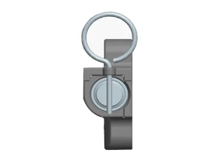
| 2. |
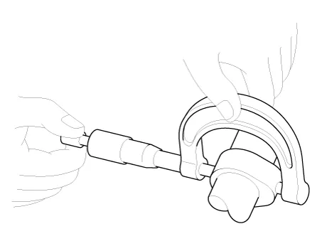
Compress the piston of the tensioner using a handy bar (A) and then insert a stopper pin (B) into the hole on the tensioner to hold the compressed piston.
|
| 3. |
Place the intake camshaft (A) and then insert the tensioner arm (B) along the timing chain.
|
| 4. |
Place the exhaust camshaft (A).
|
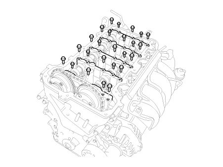
| 5. |
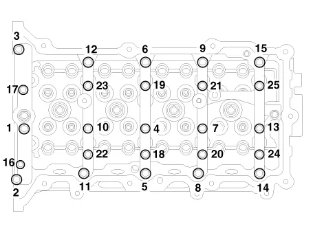
Install the camshaft bearing caps.
Tighten the bolts, in several passes, in the sequence as shown.
|
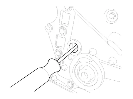
| 6. |
Using a suitable tool, move the tensioner arm to align the tensioner bolt hole with the service hole.
|
| 7. |
Install the tensioner arm bolt (A).
|
| 8. |
Remove the stopper pin from the tensioner. |
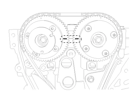
| 9. |
Turn the crankshaft two turns in the operating direction (clockwise), and then check that the TDC marks of the CVVT sprockets are in straight line on the cylinder head surface.
|
| 10. |
Install a service plug bolt (A) with a gasket.
|
| 11. |
Install the other parts reverse order of removal. |
Components and components location Components 1. Cylinder head cover 2. Cylinder head cover gasket Repair procedures Removal • Use fender covers to avoid damaging painted surfaces.
Components and components location Components 1. Camshaft bearing cap 2. Camshaft front bearing cap 3. Exhaust camshaft 4.
Other information:
Kia Optima DL3 2019-2026 Service and Repair Manual: Auto Defogging Sensor
Description and operation Description The auto defogging sensor is installed on the front window glass. The sensor judges and sends signal if moisture occurs to blow out wind for defogging. The air conditioner control module receives signal from the sensor and restrains moisture and eliminate defog by controlling the intake actu
Kia Optima DL3 2019-2026 Service and Repair Manual: Temperature Control Actuator
Components and components location Components Location 1. Temperature control actuator [LH] 2. Temperature control actuator [RH] Description and operation Description The temperature control actuator is located at the heater unit.
Categories
- Manuals Home
- Kia Optima Owners Manual
- Kia Optima Service Manual
- Body Electrical System
- Headlamps
- Body (Interior and Exterior)
- New on site
- Most important about car
