Kia Optima DL3: Engine Control System / Engine Control Module (ECM)
Components and components location
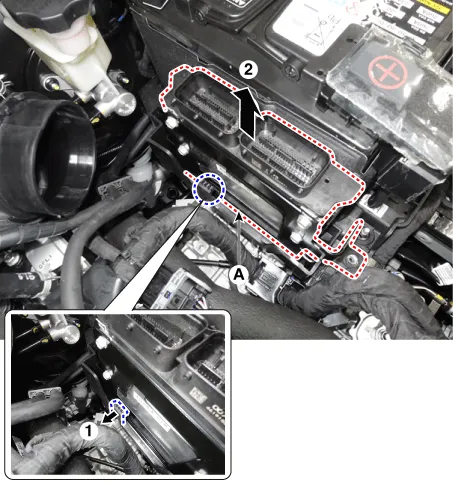
| Component Location |
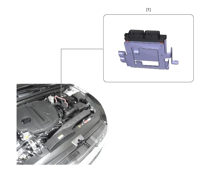
| 1. Engine Control Module (ECM)
|
Schematic diagrams
| Connector and Terminal function |
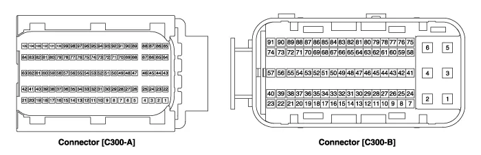
| ECM Terminal Function |
[Connector A]
|
Pin |
Function |
Connected to |
|
1 |
- |
|
|
2 |
ETC Motor [+] control output |
ETC Motor |
|
3 |
- |
|
|
4 |
- |
|
|
5 |
- |
|
|
6 |
- |
|
|
7 |
- |
|
|
8 |
- |
|
|
9 |
- |
|
|
10 |
- |
|
|
11 |
- |
|
|
12 |
- |
|
|
13 |
- |
|
|
14 |
- |
|
|
15 |
Sensor ground |
Engine Coolant Temperature Sensor (ECTS) |
|
16 |
Engine Coolant Temperature Sensor (ECTS) signal input |
Engine Coolant Temperature Sensor (ECTS) |
|
17 |
Throttle Position Sensor (TPS) 2 signal input |
Throttle Position Sensor (TPS) 2 [ETC Module] |
|
18 |
- |
|
|
19 |
- |
|
|
20 |
- |
|
|
21 |
Sensor power (+5V) |
Manifold Absolute Pressure Sensor (MAPS) |
|
Camshaft Position Sensor (CMPS) [Bank 1 / Intake] |
||
|
22 |
- |
|
|
23 |
ETC Motor [-] control output |
ETC Motor [ETC Module] |
|
24 |
- |
|
|
25 |
- |
|
|
26 |
- |
|
|
27 |
- |
|
|
28 |
- |
|
|
29 |
- |
|
|
30 |
- |
|
|
31 |
Electrical load signal input (FR) |
Alternator |
|
32 |
- |
|
|
33 |
- |
|
|
34 |
- |
|
|
35 |
- |
|
|
36 |
- |
|
|
37 |
Sensor ground |
Throttle Position Sensor (TPS) 1, 2 [ETC Module] |
|
38 |
Throttle Position Sensor (TPS) 1 signal input |
Throttle Position Sensor (TPS) 1 [ETC Module] |
|
39 |
- |
|
|
40 |
Alternator PWM control output |
Alternator |
|
41 |
- |
|
|
42 |
Sensor power (+5V) |
Throttle Position Sensor (TPS) 1, 2 [ETC Module] |
|
43 |
- |
|
|
44 |
- |
|
|
45 |
- |
|
|
46 |
- |
|
|
47 |
- |
|
|
48 |
- |
|
|
49 |
- |
|
|
50 |
- |
|
|
51 |
- |
|
|
52 |
- |
|
|
53 |
- |
|
|
54 |
- |
|
|
55 |
- |
|
|
56 |
Sensor ground |
Camshaft Position Sensor (CMPS) [Bank 1/Exhaust] |
|
57 |
- |
|
|
58 |
- |
|
|
59 |
- |
|
|
60 |
- |
|
|
61 |
Sensor ground |
Manifold Absolute Pressure Sensor (MAPS) |
|
62 |
Manifold Absolute Pressure Sensor (MAPS) signal input |
Manifold Absolute Pressure Sensor (MAPS) |
|
63 |
Sensor power (+5V) |
Camshaft Position Sensor (CMPS) [Bank 1 / Exhaust] |
|
65 |
- |
|
|
66 |
- |
|
|
67 |
- |
|
|
68 |
- |
|
|
69 |
- |
|
|
70 |
- |
|
|
71 |
- |
|
|
72 |
- |
|
|
73 |
- |
|
|
74 |
Sensor ground |
Crankshaft Position Sensor (CKPS) |
|
75 |
- |
|
|
76 |
- |
|
|
77 |
Camshaft Position Sensor (CMPS) [Bank 1 / Exhaust] signal input |
Camshaft Position Sensor (CMPS) [Bank 1 / Exhaust] |
|
78 |
Sensor ground |
Camshaft Position Sensor (CMPS) [Bank 1 / Intake] |
|
79 |
- |
|
|
80 |
- |
|
|
81 |
- |
|
|
82 |
- |
|
|
83 |
VG (Virtual Ground) |
Heated Oxygen Sensor [Bank 1 / Sensor 1] |
|
84 |
VRC (Current Adjust) |
Heated Oxygen Sensor [Bank 1 / Sensor 1] |
|
85 |
- |
|
|
86 |
- |
|
|
87 |
- |
|
|
88 |
- |
|
|
89 |
- |
|
|
90 |
- |
|
|
91 |
- |
|
|
92 |
- |
|
|
93 |
- |
|
|
94 |
- |
|
|
95 |
Crankshaft Position Sensor (CKPS) signal input |
Crankshaft Position Sensor (CKPS) |
|
96 |
- |
|
|
97 |
- |
|
|
98 |
Camshaft Position Sensor (CMPS) [Bank 1 / Intake] signal input |
Camshaft Position Sensor (CMPS) [Bank 1 / Intake] |
|
99 |
Sensor ground |
Knock Sensor (KS) |
|
100 |
Knock Sensor (KS) signal input |
Knock Sensor (KS) |
|
101 |
Intake Air Temperature Sensor (IATS) signal input |
Intake Air Temperature Sensor (IATS) |
|
102 |
- |
|
|
103 |
- |
|
|
104 |
VN (NERNST Cell Voltage) |
Heated Oxygen Sensor (HO2S) [Bank 1 / Sensor 1] |
|
105 |
VIP (Current Pump) |
Heated Oxygen Sensor [Bank 1 / Sensor 1] |
[Connector B]
|
Pin |
Function |
Connected to |
|
1 |
Power ground |
Chassis Ground |
|
2 |
Power ground |
Chassis Ground |
|
3 |
Battery power (B+) |
Main Relay |
|
4 |
Power ground |
Chassis Ground |
|
5 |
Battery power (B+) |
Main Relay |
|
6 |
Battery power (B+) |
Main Relay |
|
7 |
- |
|
|
8 |
- |
|
|
9 |
- |
|
|
10 |
Accelerator Position Sensor (APS) 2 signal input |
Accelerator Position Sensor (APS) 2 |
|
11 |
A/C Pressure Transducer (APT) signal input |
A/C Pressure Transducer (APT) |
|
12 |
- |
|
|
13 |
- |
|
|
14 |
Sensor power (+5V) |
A/C Pressure Transducer (APT) |
|
15 |
- |
|
|
16 |
Sensor power (+5V) |
Accelerator Position Sensor (APS) 2 |
|
17 |
Sensor power (+5V) |
Accelerator Position Sensor (APS) 1 |
|
18 |
Main Relay control output |
Main Relay |
|
19 |
Fuel Pump Relay control output |
Fuel Pump Relay |
|
20 |
- |
|
|
21 |
- |
|
|
22 |
Injector (Cylinder #2) control output |
Injector (Cylinder #3) |
|
23 |
Injector (Cylinder #3) control output |
Injector (Cylinder #3) |
|
24 |
- |
|
|
25 |
- |
|
|
26 |
- |
|
|
27 |
Accelerator Position Sensor (APS) 1 signal input |
Accelerator Position Sensor (APS) 1 |
|
28 |
Sensor ground |
Heated Oxygen Sensor (HO2S) [Bank 1 / Sensor 2] |
|
29 |
Heated Oxygen Sensor (HO2S) [Bank 1 / Sensor 2] signal input |
Heated Oxygen Sensor (HO2S) [Bank 1 / Sensor 2] |
|
30 |
- |
|
|
31 |
- |
|
|
32 |
- |
|
|
33 |
- |
|
|
34 |
Start Motor relay control output |
Start Motor relay |
|
35 |
CVVT Oil Control (OCV) Valve [Bank 1 / Exhaust] control output |
CVVT Oil Control Valve (OCV) [Bank 1 / Exhaust] |
|
36 |
CVVT Oil Control (OCV) Valve [Bank 1 / Intake] control output |
CVVT Oil Control Valve (OCV) [Bank 1 / Intake] |
|
37 |
- |
|
|
38 |
A/C Relay control output |
A/C Relay |
|
39 |
Injector (Cylinder #4) control output |
Injector (Cylinder #3) |
|
40 |
Ignition Coil (Cylinder #2) control output |
Ignition Coil (Cylinder #2) |
|
41 |
Battery power (B+) |
Ignition Switch |
|
42 |
- |
|
|
43 |
- |
|
|
44 |
- |
|
|
45 |
Sensor ground |
Accelerator Position Sensor (APS) 1 |
|
46 |
Sensor ground |
Accelerator Position Sensor (APS) 2 |
|
47 |
- |
|
|
48 |
- |
|
|
49 |
- |
|
|
50 |
Sensor ground |
A/C Pressure Transducer (APT) |
|
51 |
- |
|
|
52 |
- |
|
|
53 |
- |
|
|
54 |
- |
|
|
55 |
- |
|
|
56 |
Injector (Cylinder #1) control output |
Injector (Cylinder #1) |
|
57 |
Ignition Coil (Cylinder #4) control output |
Ignition Coil (Cylinder #4) |
|
58 |
- |
|
|
59 |
LOCAL-CAN [Low] |
Other control module, Data Link Connector (DLC) |
|
60 |
P-CAN [Low] |
Other control module, Data Link Connector (DLC) |
|
61 |
Fuel Tank Level Sensor signal input |
Fuel Tank Level Sensor (FLS) |
|
62 |
- |
|
|
63 |
- |
|
|
64 |
- |
|
|
65 |
Brake Light Switch signal input |
Brake Switch |
|
66 |
Start signal input |
Ignition Switch |
|
67 |
Engine speed signal output |
Power Distribution Module (PDM) |
|
68 |
Immobilizer communication line |
Immobilizer control module |
|
69 |
- |
|
|
70 |
- |
|
|
71 |
Purge Control Solenoid Valve (PCSV) control output |
Purge Control Solenoid Valve (PCSV) |
|
72 |
- |
|
|
73 |
Heated Oxygen Sensor (HO2S) [Bank 1 / Sensor 1] Heater control output
|
Heated Oxygen Sensor (HO2S) [Bank 1 / Sensor 1] |
|
74 |
Ignition Coil (Cylinder #3) control output |
Ignition Coil (Cylinder #3) |
|
75 |
Memory power (B+) |
Engine Room Fuse & Relay Box (EMS ECU) |
|
76 |
LOCAL-CAN [High] |
Other control module, Data Link Connector (DLC) |
|
77 |
C-CAN [High] |
Other control module, Data Link Connector (DLC) |
|
78 |
- |
|
|
79 |
Vehicle speed signal input |
ABS/ESC Control Unit |
|
80 |
- |
|
|
81 |
Wiper Switch Input Signal |
Integrated Body Control Unit (IBU) |
|
82 |
- |
|
|
83 |
Brake Test Switch signal input |
Brake Switch |
|
84 |
- |
|
|
85 |
- |
|
|
86 |
Cooling Fan Relay control output |
Cooling Fan Relay |
|
87 |
- |
|
|
88 |
Variable Intake Solenoid (VIS) Valve control output |
Variable Intake Solenoid (VIS) Valve |
|
89 |
- |
|
|
90 |
Heated Oxygen Sensor (HO2S) [Bank 1 / Sensor 2] Heater control output
|
Heated Oxygen Sensor (HO2S) [Bank 1 / Sensor 2] |
|
91 |
Ignition Coil (Cylinder #1) control output |
Ignition Coil (Cylinder #1) [NON-Immobilizer type] |
Repair procedures
| Inspection |
| 1. |
The engine control system can be more quickly diagnosed for troubles by using the vehicle diagnostic system (KDS). (Refer to "DTC guide") KDS provides the following information.
|
| Component inspection |
| 1. |
Test ECM ground circuit : Measure resistance between ECM and chassis ground using the backside of ECM harness connector as ECM side check point. If the problem is found, repair it.
|
| 2. |
Test ECM connector : Disconnect the ECM connector and visually check the ground terminals on ECM side and harness side for bent pins or poor contact pressure. If the problem is found, repair it. |
| 3. |
If problem is not found in Step 1 and 2, the ECM could be faulty. If so, make sure there were no DTC's before swapping the ECM with a new one, and then check the vehicle again. If DTC's were found, examine this first before swapping ECM. |
| 4. |
Re-test the original ECM: Install the original ECM (may be broken) into a known-good vehicle and check the vehicle. If the problem occurs again, replace the original ECM with a new one. If problem does not occur, this is intermittent problem. |
| Removal |
| 1. |
Disconnect the negative battery terminal. |
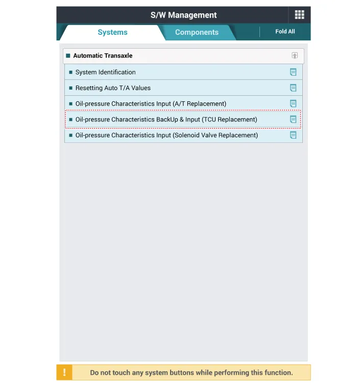
| 2. |
Perform the oil pressure characteristics backup procedure using the KDS when replacing with a new ECM.
|
| 3. |
Remove the air cleaner assembly. (Refer to Engine Mechanical System - "Air Cleaner") |
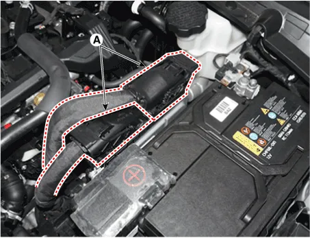
| 4. |
Disconnect the ECM connector (A).
|
| 5. |
Remove the TCM (A) by pulling it in the direction of arrow.
|
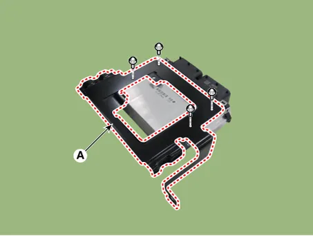
| 6. |
Remove the bracket (A) by loosening the bolts.
|
| Installation |
| 1. |
Install in the reverse order of removal. |
| 2. |
Perform the ECM reset and learning procedure by using the KDS after replacing the ECM. (Engine Control Module (ECM) - "Adjustment") |
| Adjustment |
Perform the following procedure when replacing ECM (New parts / Reused parts). |

| 1. |
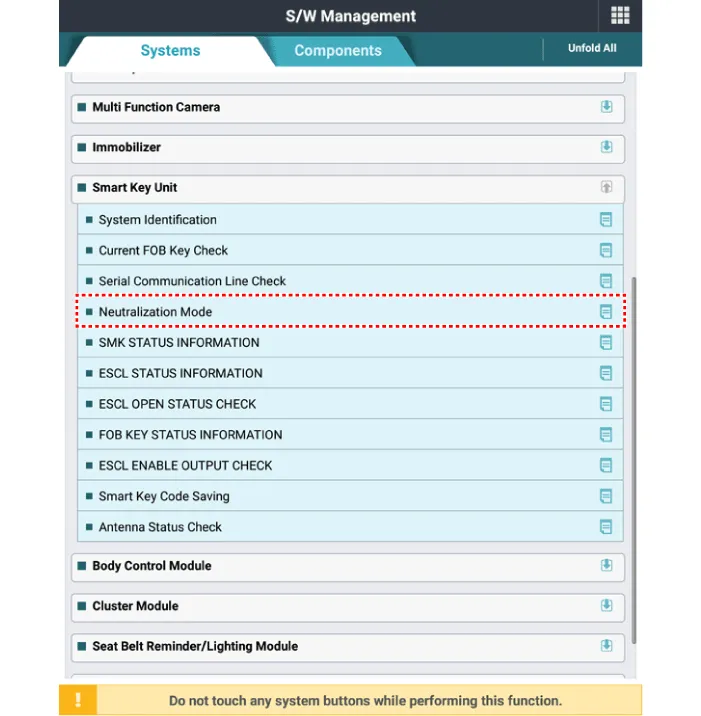
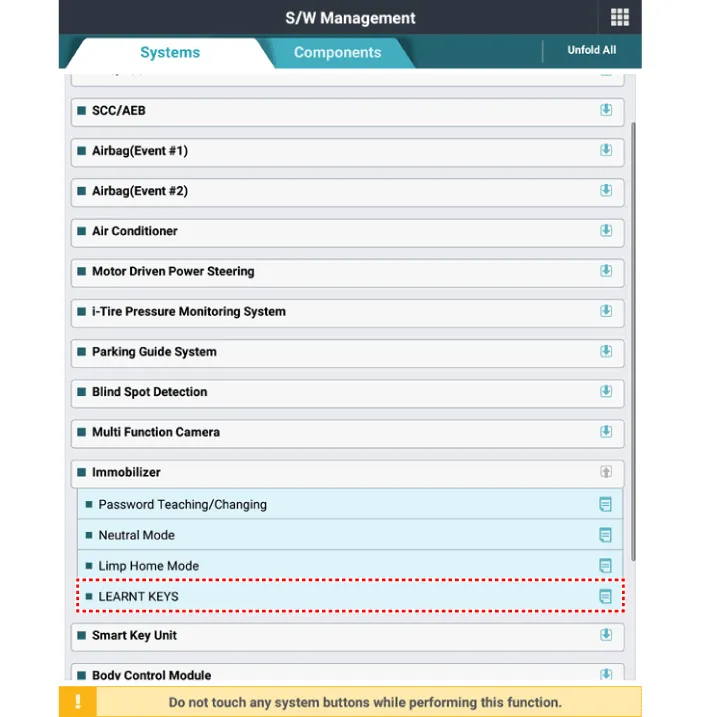
Perform the neutral mode using the KDS when replacing with a reused ECM. [Non-Smart Key]
[Smart Key]
|

| 2. |
Perform the "Key Teaching" procedure by using the KDS. [Non-Smart Key]
[Smart Key] Turn IGN ON then OFF using the smart key or start button. Then the ECM learns information on the smart key automatically. |
| 3. |
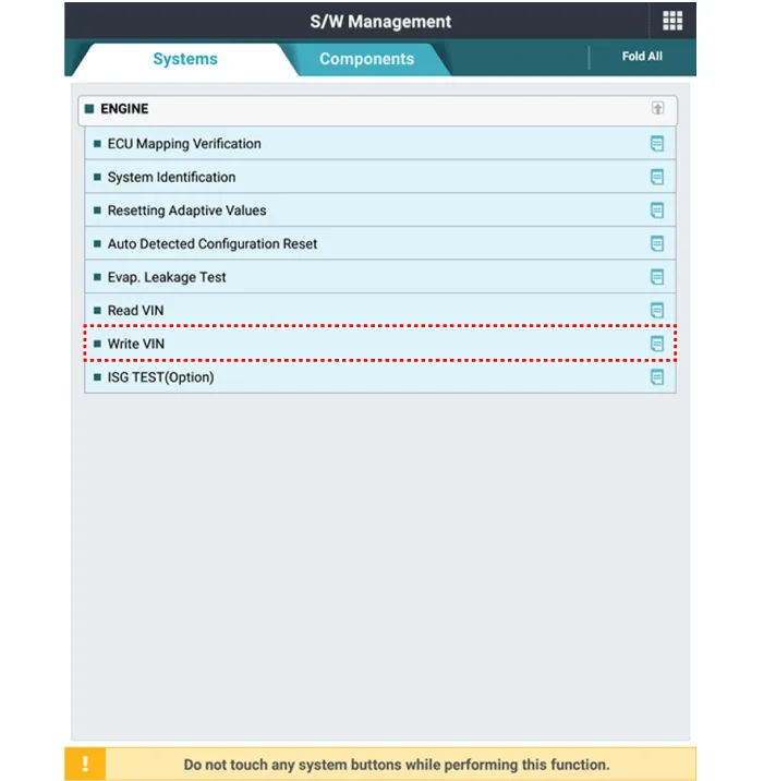
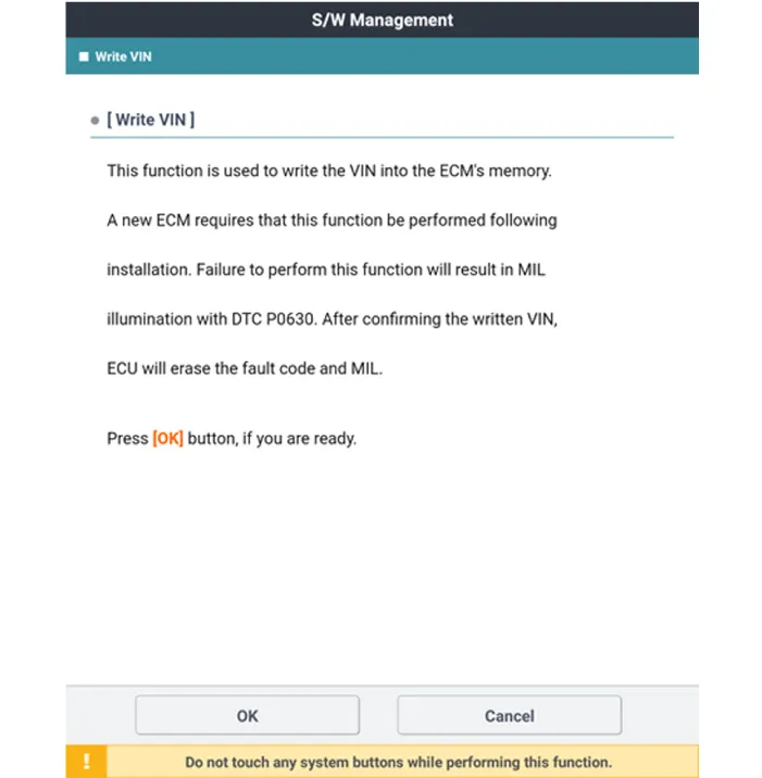
Perform the VIN writing procedure by using the KDS.
|
| 4. |
Perform the oil pressure characteristics input procedure using the KDS.
|
| 5. |
Perform ETC module learning procedure (Refer to Electronic Throttle Control System - "Adjustment") |
| 6. |
Perform TCM learning procedure. (Refer to Automatic Transaxle Control System - "Adjustment") |
Description and operation Description If the Gasoline Engine Control system components (sensors, ECM, injector, etc.) fail, interruption to the fuel supply or failure to supply the proper amount of fuel for various engine operating conditions will result.
Specifications Specification Throttle angle (°) Output voltage (V) [Vref = 5.0V] TPS1 TPS2 0 0.
Other information:
Kia Optima DL3 2019-2026 Service and Repair Manual: Keyless Entry And Burglar Alarm
Specifications Specification Item Specification Operating temperature 14 - 140°F (-10 - 60°C) RF Modulation FSK RF Frequency 433.
Kia Optima DL3 2019-2026 Service and Repair Manual: Headlamps
Components and components location Component Location 1. Low beam 2. High beam 3. Daytime Running Light / Position lamp 4. Low assist beam 5. Turn signal lamp Schematic diagrams Connector and Terminal Function Connector Terminal Function
Categories
- Manuals Home
- Kia Optima Owners Manual
- Kia Optima Service Manual
- Brake System
- Body Electrical System
- Engine Control / Fuel System
- New on site
- Most important about car
