Kia Optima DL3: Crash Pad / Crash Pad Garnish
Components and components location
| Component Location |
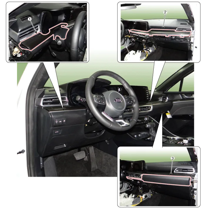
| 1. Crash pad garnish [LH] 2. Crash pad garnish [RH] |
3. Crash pad center garnish
|
Repair procedures
| Replacement |
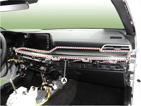
[Crash pad center garnish]
|

| 1. |
Using a screwdriver or remover, remove the crash pad side cover [LH] (A).
|
| 2. |
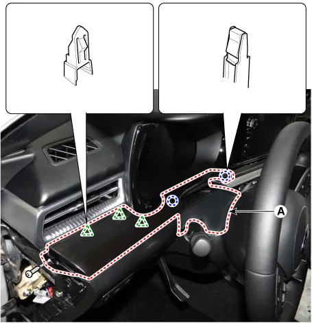
Loosen the mounting screw, using a flat-tip screwdriver and remove the crash pad center garnish (A).
|

| 3. |
To install, reverse the removal procedure.
|

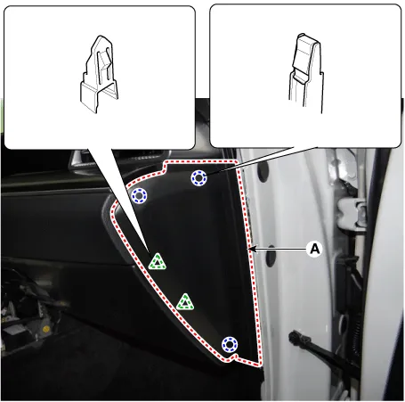
Crash pad garnish [LH]
|
| 1. |
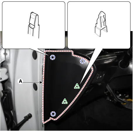
Using a screwdriver or remover, remove the crash pad side cover [LH] (A).
|
| 2. |
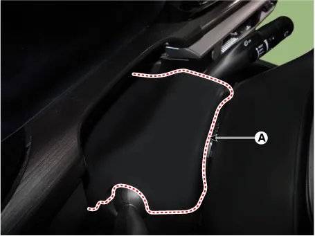
Using a screwdriver or remover, remove the steering column shroud upper panel (A).
|
| 3. |
After loosening the mounting screw, remove the crash pad garnish [LH] (A).
|
| 4. |
To install, reverse the removal procedure.
|
Crash pad garnish [RH]
|
| 1. |
Using a remover and remove the crash pad side cover [RH] (A).
|
| 2. |
After loosening the mounting screw, remove the crash pad center garnish (A).
|
| 3. |
After loosening the mounting screws, remove the crash pad garnish [RH] (A).
|
| 4. |
To install, reverse the removal procedure.
|
Components and components location Component Location 1. Steering column shroud lower panel 2. Steering column shroud upper panel Repair procedures Replacement [Steering column shroud upper panel] • When removing with a flat-tip screwdriver or remover, wrap protective tape around the tools to prevent damage to components.
Components and components location Component Location 1. Glove box Repair procedures Replacement • When removing with a flat-tip screwdriver or remover, wrap protective tape around the tools to prevent damage to components.
Other information:
Kia Optima DL3 2019-2026 Service and Repair Manual: Power Seat Motor
Components and components location Components 1. Lumbar support motor 2. Reclining motor 3. Front height motor 4. Rear height motor 5. Slide motor Repair procedures Inspection 1.
Kia Optima DL3 2019-2026 Service and Repair Manual: Refrigerant Line
Components and components location Components Location 1. Suction & Liquid tube assembly 2. Discharge hose Repair procedures Replacement 1. If the compressor is marginally operable, run the engine at idle speed, and let the air conditioning work for a few minute
Categories
- Manuals Home
- Kia Optima Owners Manual
- Kia Optima Service Manual
- Rear Brake Disc
- Automatic Transaxle System
- Body Electrical System
- New on site
- Most important about car
