Kia Optima DL3: Engine Control System / Heated Oxygen Sensor (HO2S)
Description and operation
| Description |
| • |
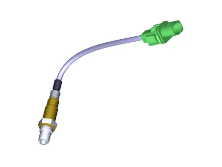
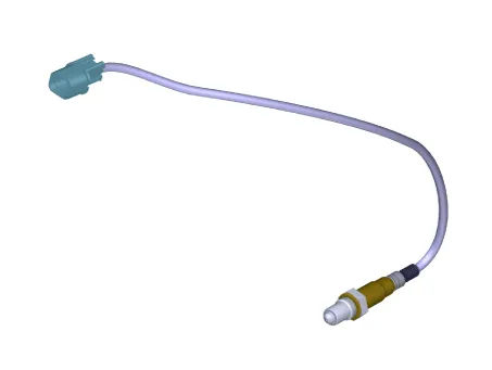
Heated Oxygen Sensor (HO2S), consisting of zirconium and alumina, is installed on both upstream and downstream of the Manifold Catalytic Converter (MCC) to detect the air/fuel ratio and send it to the ECM. |
| • |
In order that this sensor operates properly, the temperature of the sensor tip must be higher than 370°C (698°F). For this reason, a heater controlled by the ECM duty signal, is built into the sensor. When the exhaust gas temperature is lower than the specified value, the heater warms the sensor tip. |
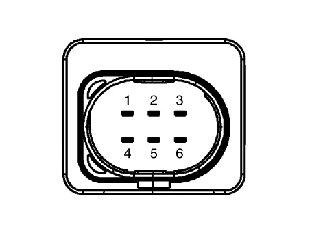
[Front Heated Oxygen Sensor]
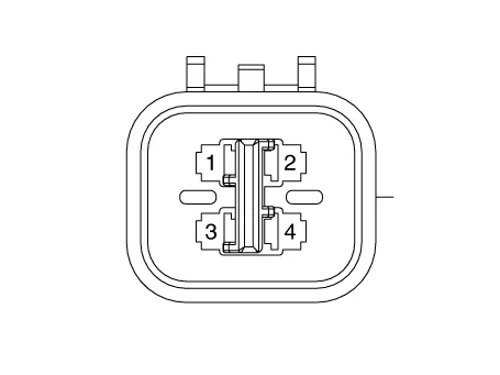
[Rear Heated Oxygen Sensor]
Components and components location
| Components Location |
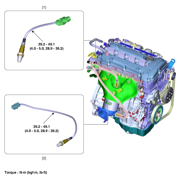
| 1. Front Heated Oxygen Sensor
|
2. Rear Heated Oxygen Sensor
|
Schematic diagrams
| Circuit Diagram |
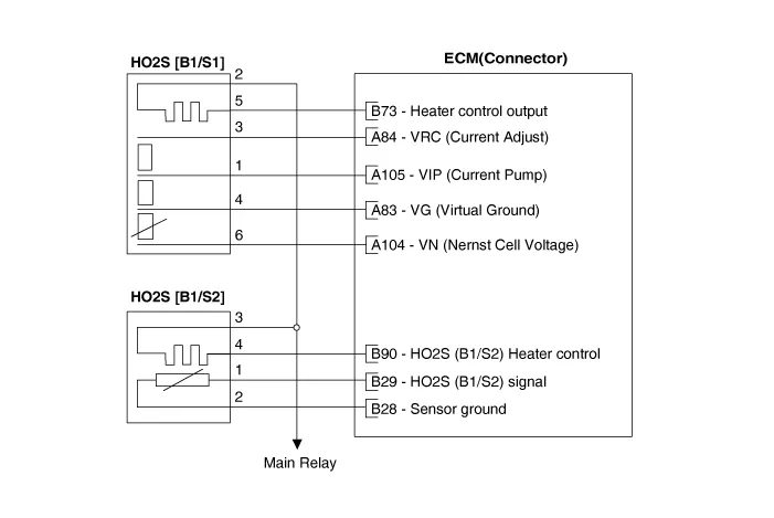
Harness Connector
[Front Heated Oxygen Sensor]
[Rear Heated Oxygen Sensor]
Repair procedures
| Inspection |
| 1. |
The engine control system can be more quickly diagnosed for troubles by using the vehicle diagnostic system (KDS). (Refer to "DTC guide") KDS provides the following information.
|
| Component Inspection |
| 1. |
Check signal waveform of HO2S using a KDS.
|
| Removal |
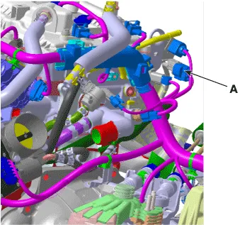
| [Front Heated Oxygen Sensor] |
| 1. |
Disconnect the negative battery terminal. |
| 2. |
Disconnect the connector (A).
|
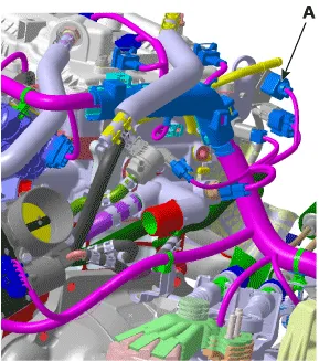
| 3. |
Remove the heated oxygen sensor (B) by using the SST (09392-1Y100)
|
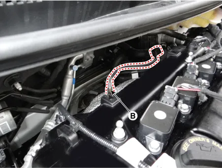
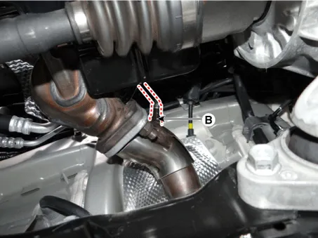
| [Rear Heated Oxygen Sensor] |
| 1. |
Disconnect the negative battery terminal. |
| 2. |
Disconnect the heated oxygen sensor connector (A).
|
| 3. |
Remove the heated oxygen sensor (B) by using the SST (09392-1Y100)
|
| Installation |
|

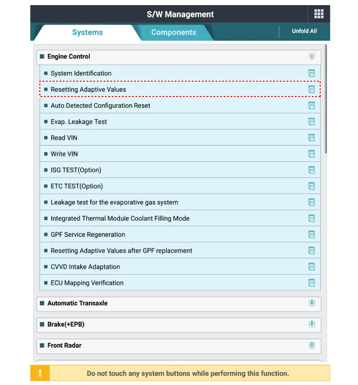
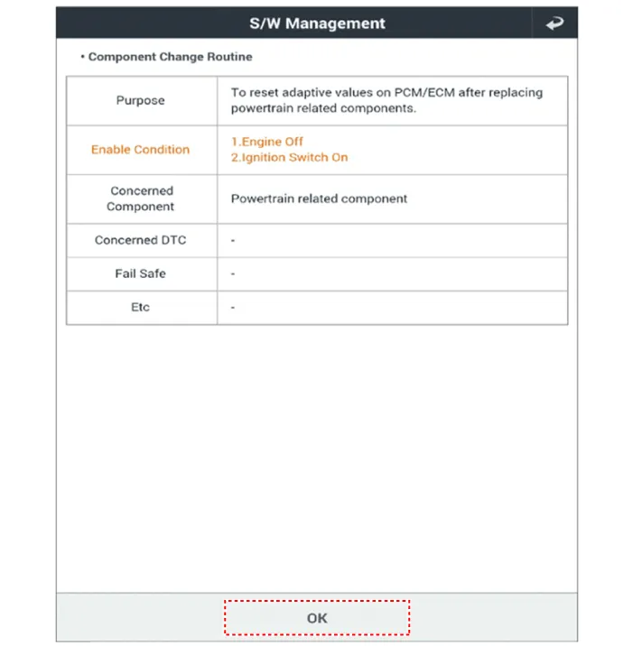
| 1. |
Install in the reverse order of removal. |
| 2. |
Reset the ECM adaptive value after replacing the heated oxygen sensor.
|
Specifications Specification Item Specification Capacitance (pF) 850 - 1,150 Description and operation Description • Knocking is a condition characterized by undesirable vibration and noise and can cause engine damage.
Specifications Specification Accelerator Output Voltage (V) [Vref = 5.0V] Position APS1 APS2 C.
Other information:
Kia Optima DL3 2019-2026 Service and Repair Manual: Power Door Locks
C
Kia Optima DL3 2019-2026 Service and Repair Manual: Ventilated and Heated Seat
Schematic diagrams Connector and Terminal Function Pin Function Connector A Connector B 1 Driver heater ground (-) Driver blower speed (+) 2 Passenger heater ground (-) - 3
Categories
- Manuals Home
- Kia Optima Owners Manual
- Kia Optima Service Manual
- Rear Brake Disc
- Steering System
- Timing Chain
- New on site
- Most important about car
