Kia Optima DL3: Crankcase Emission Control System / Positive Crankcase Ventilation (PCV) Valve
Description and operation
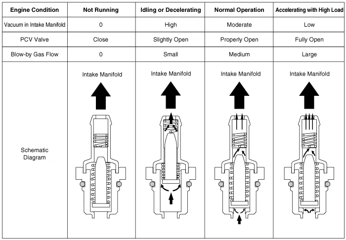
| Operation Principle |
Repair procedures
| Removal |
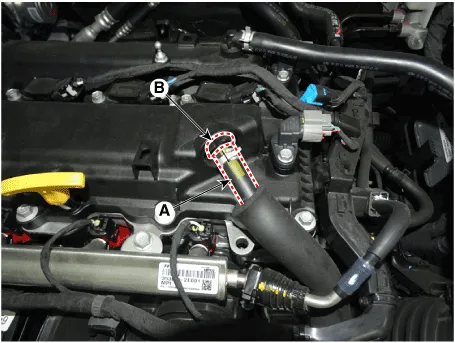
| 1. |
Disconnect the vapor hose (A). |
| 2. |
Remove the PCV valve (B).
|
| Inspection |
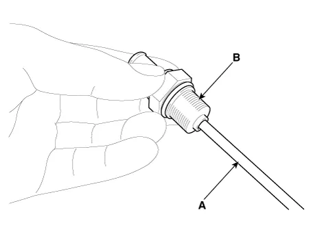
| 1. |
Insert a thin stick (A) into the PCV valve (B) from the threaded side to check that the plunger moves.
|

| Installation |
| 1. |
Install in the reverse order of removal. |
Schematic diagrams Schematic Diagram Repair procedures Inspection 1. After disconnecting the vapor hose from the PCV valve, remove the PCV valve.
Description and operation Description Evaporative Emission Control System prevents fuel vapor stored in fuel tank from vaporizing into the atmosphere.
Other information:
Kia Optima DL3 2019-2026 Service and Repair Manual: License Lamps
Repair procedures Removal 1. Disconnect the negative battery terminal. 2. Remove the lcense lamp (A) by pressing the hook. 3. Disconnect the lcense lamp connector (A).
Kia Optima DL3 2019-2026 Service and Repair Manual: Ambient Temperature Sensor
Description and operation Description The ambient temperature sensor is located at the front of the condenser and detects ambient air temperature. It is a negative type thermistor; resistance will increase with lower temperature, and decrease with higher temperature.
Categories
- Manuals Home
- Kia Optima Owners Manual
- Kia Optima Service Manual
- Front Axle Assembly
- Engine Control / Fuel System
- Timing Chain
- New on site
- Most important about car
