Kia Optima DL3: Engine Control System / Variable Charge Motion Actuator (VCMA)
Description and operation
| Description |
| • |
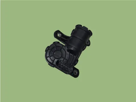
The Variable Charge Motion Actuator (VCMA) is installed on the inlet of the intake manifold. |
| • |
It consists of a DC motor which actuates the VCM valve and a position sensor which detects the position of the VCM valve. |
| • |
The VCM system tumbles air flow entering into combustion chamber of each cylinder by closing the VCM valve in the cold start conditions. |
| • |
This tumble effect reduces cold start emissions by improving atomization |
Components and components location
| Components |
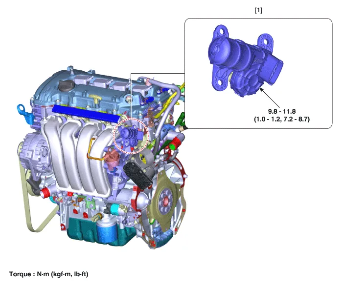
| 1. Variable Charge Motion Actuator
(VCMA) |
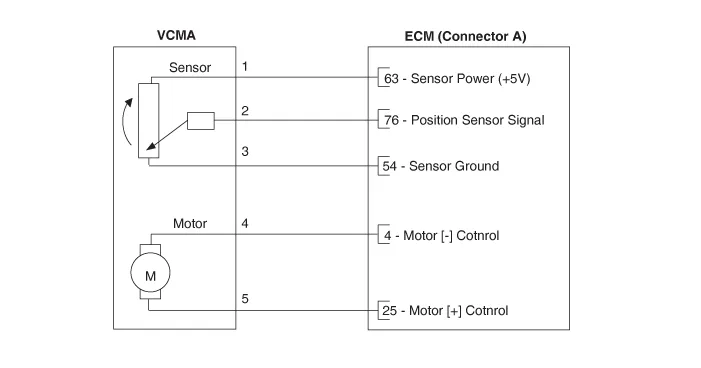
Schematic diagrams
| Circuit diagram |
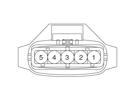
Harness Connector
Repair procedures
| Inspection |
| 1. |
The engine control system can be more quickly diagnosed for troubles by using the vehicle diagnostic system (KDS). (Refer to "DTC guide") KDS provides the following information.
|
| Removal |
| 1. |
Disconnect the negative battery terminal. |
| 2. |
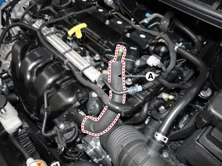
Disconnect the PCV hose (A).
|
| 3. |
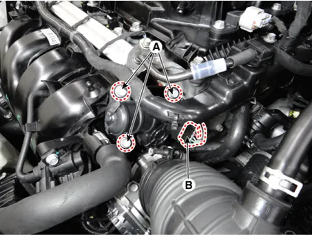
Disconnect the VCMA connector (A). |
| 4. |
Remove the VCMA mounting bolts (B).
|
| 5. |
Remove the VCMA (A).
|

| Installation |
|

| 1. |
Install in the reverse order of removal. |
Specifications Specification Item Specification Coil resistance (Ω) 30.0 - 35.0 [22°C (71.
Fuel pressure test Fuel Pressure Test 1. Release the residual pressure in fuel line. (Refer to Fuel Delivery System - "Release Residual Pressure in Fuel Line") When removing the fuel pump relay, a Diagnostic Trouble Code (DTC) may occur.
Other information:
Kia Optima DL3 2019-2026 Service and Repair Manual: Headlamps
Components and components location Component Location 1. Low beam 2. High beam 3. Daytime Running Light / Position lamp 4. Low assist beam 5. Turn signal lamp Schematic diagrams Connector and Terminal Function Connector Terminal Function
Kia Optima DL3 2019-2026 Service and Repair Manual: Mood Lamp Unit
Schematic diagrams Connector and Terminal function Repair procedures Removal When removing with a flat-tip screwdriver or remover, wrap protective tape around the tools to prevent damage to components.
Categories
- Manuals Home
- Kia Optima Owners Manual
- Kia Optima Service Manual
- Battery
- Rear Brake Disc
- Floor Console Assembly
- New on site
- Most important about car
