Kia Optima DL3: Rear Suspension System / Rear Shock Absorber
Components and components location
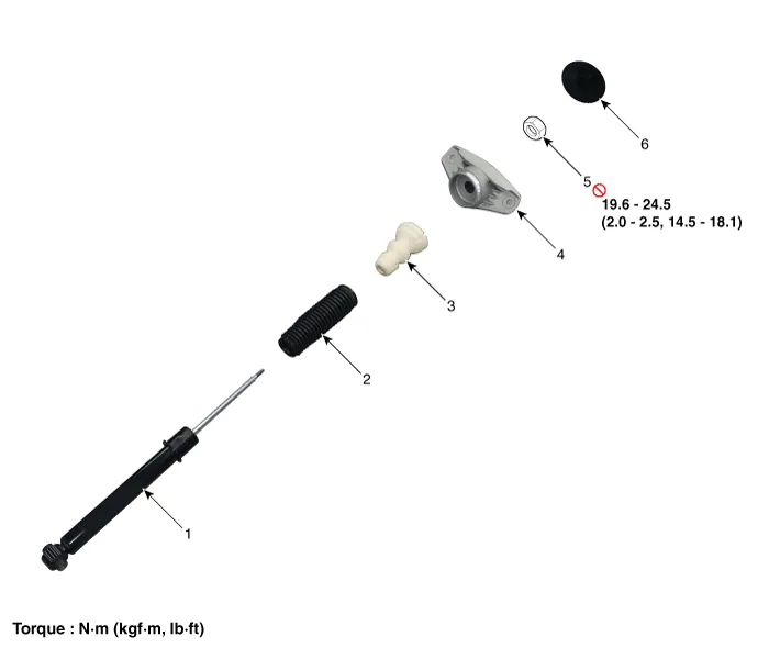
| Components |
Repair procedures
| Removal |
| 1. |
Disconnect the (-) battery terminal. |
| 2. |
Remove the rear wheel and tire. (Refer to Tires/Wheels - "Wheel") |
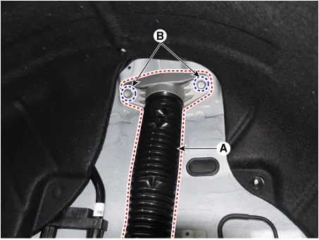
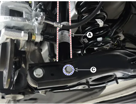
| 3. |
Remove the rear shock absorber (A). after loosening the bolts.
|
| Installation |
| 1. |
Install in the reverse order of removal. |
| 2. |
Check the alignment. (Refer to Suspension System - "Alingment") |
| Disassembly |
| 1. |
Remove the lock nut cover (A).
|
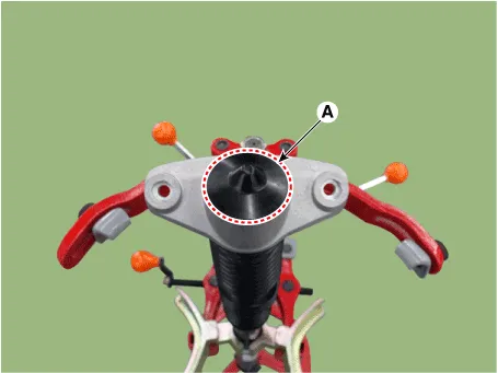
| 2. |
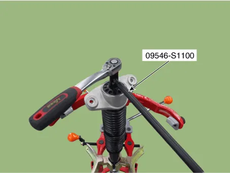
Using the special tool (09546-S1100), install the self locking nut.
|
| 3. |
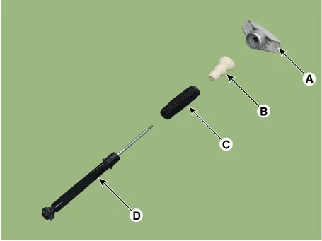
Separate the bracket assembly (A), bumper rubber (B), dust cover (C), shock absorber (D).
|
| Inspection |
| 1. |
Check the rubber parts for damage or deterioration. |
| 2. |
Check the shock absorber for abnormal resistance or unusual sounds.
|
| Disposal |
| 1. |
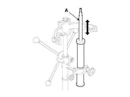
Fully extend the shock absorber rod. |
| 2. |
Drill a hole to remove gas from the cylinder.
|


| Reassembly |
| 1. |
To reassembly, reverse the disassembly procedure. |
| 2. |
Using SST(09546-S1100), install the lock nut.
|

| 3. |
Install the lock nut cover (A).
|
Components and components location Components and Components Location 1. Trailing arm 2. Rear shock absorber 3. Rear suspension 4.
Repair procedures Removal 1. Disconnect the (-) battery terminal. 2. Remove the rear wheel and tire.
Other information:
Kia Optima DL3 2019-2026 Service and Repair Manual: Room Lamp
Repair procedures Removal When removing with a flat-tip screwdriver or remover, wrap protective tape around the tools to prevent damage to components. 1.
Kia Optima DL3 2019-2026 Service and Repair Manual: Panorama Sunroof Motor
Schematic diagrams Connector and Terminal Function Repair procedures Inspection 1. Disconnect the negative battery terminal. 2. Remove the rear pillar trim [LH]. (Refer to Body - "Rear Pillar Trim") 3.
Categories
- Manuals Home
- Kia Optima Owners Manual
- Kia Optima Service Manual
- Front Axle Assembly
- Rear Brake Disc
- Timing Chain
- New on site
- Most important about car
