Kia Optima DL3: Rear Suspension System / Rear Upper Arm
Repair procedures
| Removal |
| 1. |
Disconnect the (-) battery terminal. |
| 2. |
Remove the rear wheel and tire. (Refer to Tires/Wheels - "Wheel") |
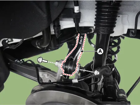
| 3. |
Loosen the bolt and nut and remove the rear upper arm (A).
|
| Inspection |
| 1. |
Check the bushing for wear and deterioration. |
| 2. |
Check for all bolts and nuts. |
| Installation |
| 1. |
Install in the reverse order of removal. |
| 2. |
Check the alignment. (Refer to Suspension System - "Alingment") |
Repair procedures Removal 1. Disconnect the (-) battery terminal. 2. Remove the rear wheel and tire.
Repair procedures Removal 1. Disconnect the (-) battery terminal. 2. Remove the rear wheel and tire.
Other information:
Kia Optima DL3 2019-2026 Service and Repair Manual: Power Door Lock Switch
Repair procedures Inspection Power Window Main Switch Diagnosis With KDS 1. In the body electrical system, failure can be quickly diagnosed by using the vehicle diagnostic system (KDS). The diagnostic system (KDS) provides the following information.
Kia Optima DL3 2019-2026 Service and Repair Manual: Smart Key
Repair procedures Adjustment Smart Key Code Saving 1. Connect the VCI II in driver side crash pad lower panel, turn the power on KDS. 2. Select the vehicle model and then do "Smart key code saving".
Categories
- Manuals Home
- Kia Optima Owners Manual
- Kia Optima Service Manual
- Engine Control / Fuel System
- CVVT Oil Control Valve (OCV)
- Emergency trunk safety release
- New on site
- Most important about car
