Kia Optima DL3: Starting System / Starter
Description and operation
| Description |
The starting system includes the battery, starter, solenoid switch, ignition switch, inhibitor switch (A/T), clutch pedal switch (M/T), ignition lock switch, connection wires and the battery cable.
When the ignition key is turned to the start position, current flows and energizes the starter motor's solenoid coil.
The solenoid plunger and clutch shift lever are activated, and the clutch pinion engages the ring gear.The contacts close and the starter motor cranks.
In order to prevent damage caused by excessive rotation of the starter armature when the engine starts, the clutch pinion gear overruns.
Specifications
| Specification |
|
Item |
Specification |
|
|
Rated voltage |
12V, 1.2 kW |
|
|
The number of pinion teeth |
13 |
|
|
Performance [No-load, 11V] |
Ampere |
70A |
|
Speed |
Min. 2,400 rpm |
|
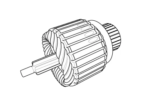
Components and components location
| Components |
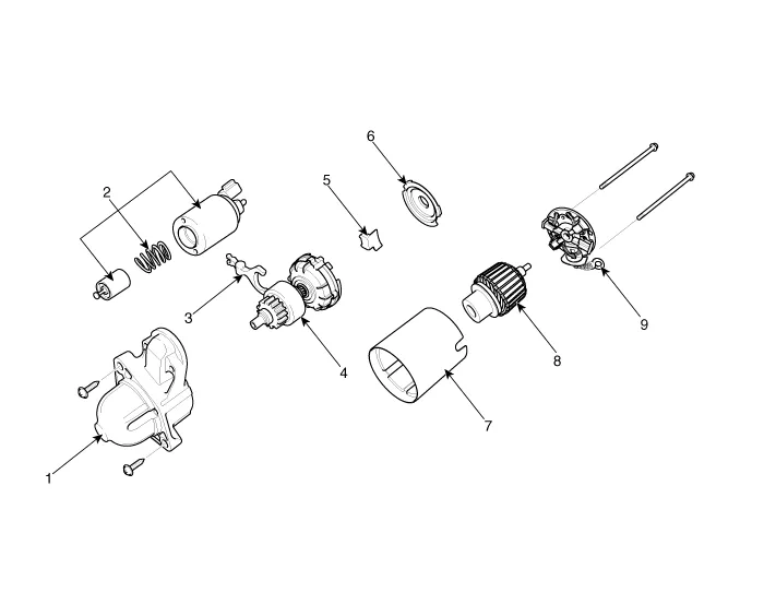
| 1. Front bracket assembly 2. Magnet switch assembly 3. Lever 4. Reducer assembly 5. Lever stop |
6. Gasket sheet 7. Yoke assembly 8. Armature assembly 9. Brush holder assembly |
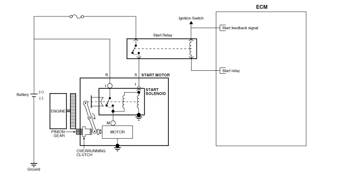
Schematic diagrams
| Circuit Diagram |
Repair procedures
| Removal |
| 1. |
Disconnect the negative battery (-) terminal. |
| 2. |
Remove the air cleaner assembly. (Refer to Engine Mechanical System - "Air Cleaner") |
| 3. |
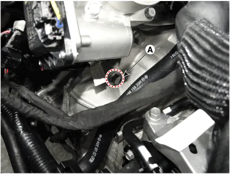
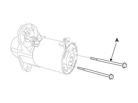
Remove the starter mounting upper bolt (A).
|
| 4. |
Remove the engine room under cover. (Refer to Engine Mechanical System - "Engine Room Under Cover") |
| 5. |
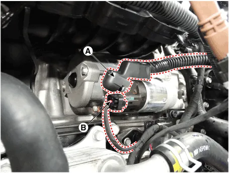
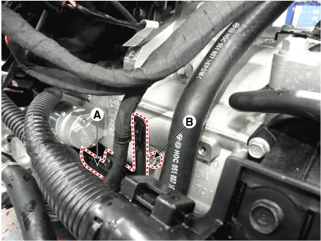
Disconnect the starter cable (A) from the B terminal on the solenoid, then disconnect the connector (B) from the S terminal.
|
| 6. |
Remove the wiring bracket (A). |
| 7. |
Remove the starter mounting lower bolt (B).
|
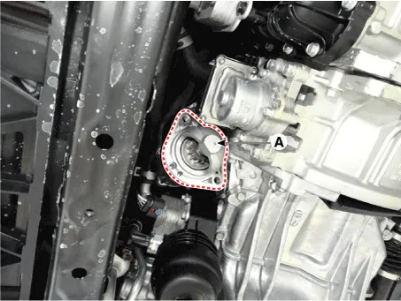
| 8. |
Remove the starter (A).
|
| Installation |
| 1. |
Install in the reverse order of removal. |
| Disassembly |
| 1. |
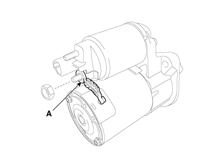
Disconnect the M-terminal (A) on the magnet switch assembly.
|
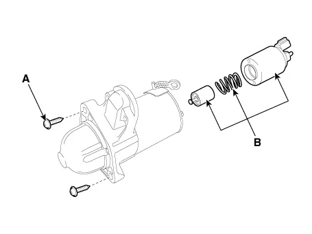
| 2. |
After loosening the screws (A), detach the magnet switch ssembly (B).
|
| 3. |
Loosen the through bolts (A).
|
| 4. |
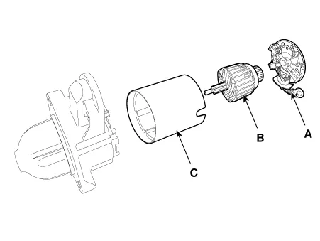
Remove the brush holder assembly (A), armature assembly (B) and yoke assembly (C).
|
| 5. |
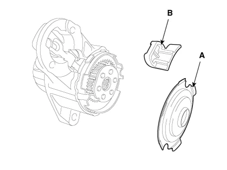
Remove the gasket sheet (A) and lever stop (B).
|
| 6. |
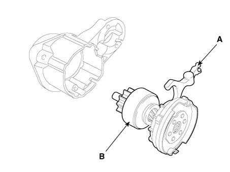
Remove the reducer assembly (A) and lever (B).
|
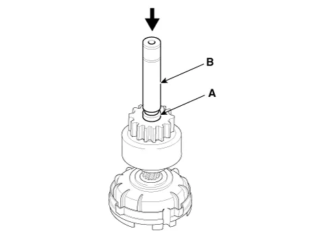
| 7. |
Press the stopper (A) using a socket (B).
|
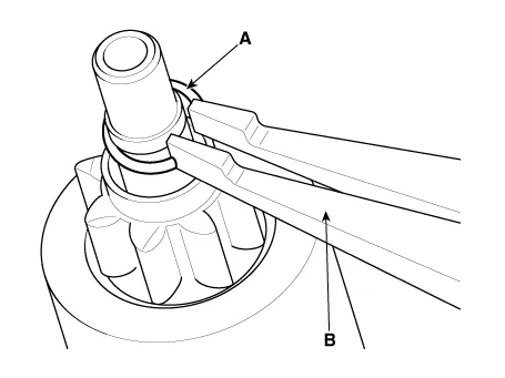
| 8. |
After removing the stop ring (A) using stop ring pliers (B).
|
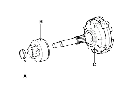
| 9. |
Disconnect the stopper (A), overrunning clutch (B) and internal gear (C).
|

| 10. |
Reassembly is the reverse of disassembly. |
| Inspection |
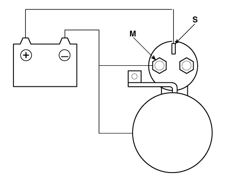
Starter Solenoid Inspection
| 1. |
Disconnect the lead wire from the M-terminal of solenoid switch. |
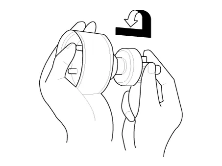
| 2. |
Connect the battery as shown. If the starter pinion pops out, it is working properly.
|
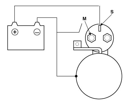
| 3. |
Disconnect the battery from the M terminal. If the pinion does not retract, the hold-in coil is working properly.
|
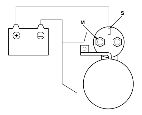
| 4. |
Disconnect the battery also from the body. If the pinion retracts immediately, it is working properly.
|
Free Running Inspection
| 1. |
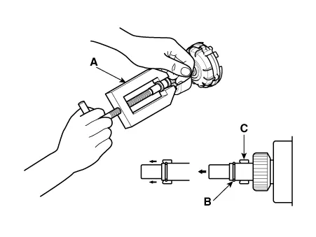
Place the starter motor in a vise equipped with soft jaws and connect a fully-charged 12-volt battery to starter motor as follows. |
| 2. |
Connect a test ammeter (150-ampere scale) and carbon pile rheostats shown is the illustration. |
| 3. |
Connect a voltmeter (15-volt scale) across starter motor.
|
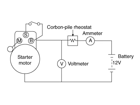
| 4. |
Rotate carbon pile to the off position. |
| 5. |
Connect the battery cable from battery's negative post to the starter motor body. |
| 6. |
Adjust until battery voltage shown on the voltmeter reads 11 volts. |
| 7. |
Confirm that the maximum amperage is within the specifications and that the starter motor turns smoothly and freely.
|
Armature Inspection And Test
| 1. |
Remove the starter. |
| 2. |
Disassemble the starter as shown at the beginning of this procedure. |
| 3. |
Inspect the armature for wear or damage from contact with the permanent magnet. If there is wear or damage, replace the armature.
|
| 4. |
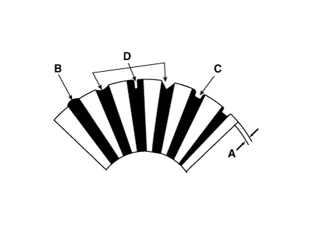
Check the commutator (A) surface. If the surface is dirty or burnt, resurface with emery cloth or a lathe within the following specifications, or recondition with #500 or #600 sandpaper (B).
|
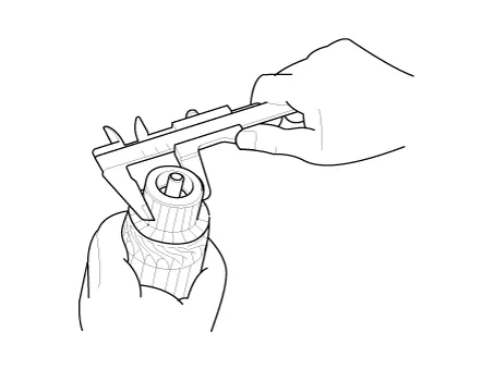
| 5. |
Check the commutator diameter. If the diameter is below the service limit, replace the armature.
|
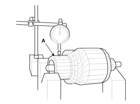
| 6. |
Measure the commutator (A) runout.
|
| 7. |
Check the mica depth (A). If the mica is too high (B), undercut the mica with a hacksaw blade to the proper depth. Cut away all the mica (C) between the commutator segments. The undercut should not be too shallow, too narrow, or v-shaped (D).
|
| 8. |
Check for continuity between the segments of the commutator. If an open circuit exists between any segments, replace the armature.
|
| 9. |
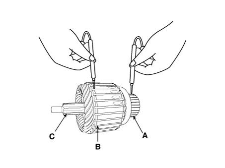
Check with an ohmmeter that no continuity exists between the commutator (A) and armature coil core (B), and between the commutator and armature shaft (C). If continuity exists, replace the armature.
|
Inspect Starter Brush
Brushes that are worm out, or oil-soaked, should be replaced.

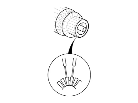
Starter Brush Holder Test
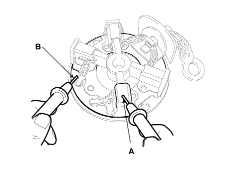
Make sure there is no continuity between the (+) brush holder (A) and (-) plate (B). If there is continuity, replace the brush holder assembly.
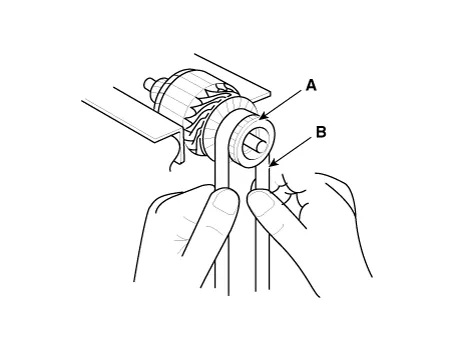
Overrunning Clutch
| 1. |
Slide the overrunning clutch along the shaft. Replace it if does not slide smoothly. |
| 2. |
Rotate the overrunning clutch both ways. Does it lock in one direction and rotate smoothly in reverse? If it does not lock in either direction or it locks in both directions, replace it.
|
| 3. |
If the starter drive gear is worn or damaged, replace the overrunning clutch assembly. (the gear is not available separately). Check the condition of the flywheel or torque converter ring gear if the starter drive gear teeth are damaged. |
| Cleaning |
| 1. |
Do not immerse parts in cleaning solvent. Immersing the yoke assembly and/or armature will damage the insulation. Wipe these parts with a cloth only. |
| 2. |
Do not immerse the drive unit in cleaning solvent. The overrun clutch is pre-lubricated at the factory and solvent will wash lubrication from the clutch. |
| 3. |
The drive unit may be cleaned with a brush moistened with cleaning solvent and wiped dry with a cloth. |
Description and operation Description The starting system includes the battery, starter, solenoid switch, ignition switch, inhibitor switch (A/T), clutch pedal switch (M/T), ignition lock switch, connection wires and the battery cable.
Repair procedures Inspection 1. Disconnect the negative battery (-) terminal. 2. Remove the fuse box cover.
Other information:
Kia Optima DL3 2019-2026 Service and Repair Manual: Integrated Memory Seat (IMS) Switch
Schematic diagrams Connector and Terminal Function Repair procedures Removal When prying with a flat-tip screwdriver or use a prying trim tool, wrap it with protective tape, and apply protective tape around the related parts, to prevent dam
Kia Optima DL3 2019-2026 Service and Repair Manual: Evaporator Temperature Sensor
Description and operation Description The evaporator temperature sensor will detect the evaporator core temperature and interrupt compressor relay power in order to prevent evaporator from freezing by excessive cooling. The evaporator temperature sensor has the Negative Temperature Coefficient (NTC).
Categories
- Manuals Home
- Kia Optima Owners Manual
- Kia Optima Service Manual
- Battery
- Engine Control Module (ECM)
- Heating, Ventilation and Air Conditioning
- New on site
- Most important about car
