Kia Optima DL3: Fuel Delivery System / Delivery Pipe
Components and components location
| Components |
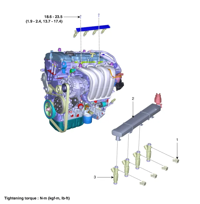
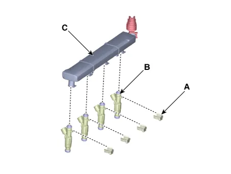
| 1. Clip 2. Delivery Pipe |
3. Injector |
Repair procedures
| Removal |
| 1. |
Release the residual pressure in fuel line. (Refer to Fuel Delivery System - "Release Residual Pressure in Fuel Line")
|

| 2. |
Disconnect the negative battery terminal. |
| 3. |
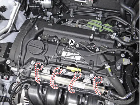
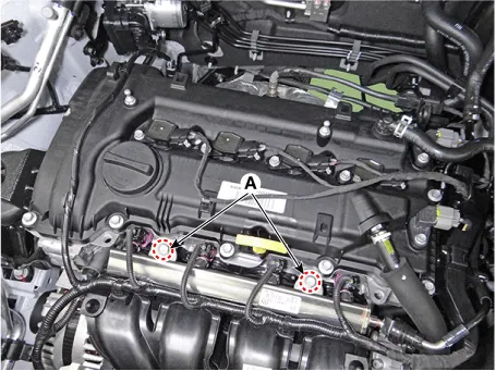
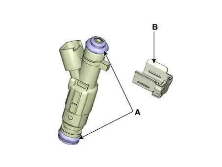
Disconnect the injector connector (A).
|
| 4. |
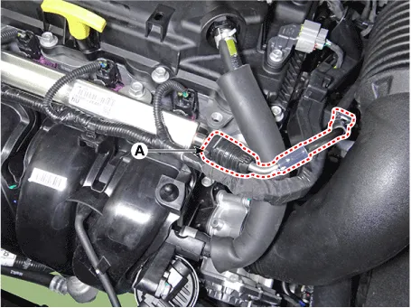
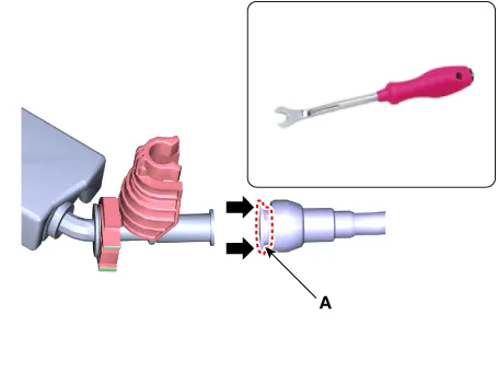
Separate the fuel feed tube quick-connector (A).
|

| 5. |
Remove the delivery pipe & injector assembly (B) after loosening the mounting bolts (A).
|
| 6. |
Separate the injector (B) from the delivery pipe (A) after removing the clip (C).
|
| Installation |
| 1. |
Install in the reverse order of removal. |
Note the followings when mounting the injector on the delivery pipe.
|
Components and components location Components 1. Filler-Neck Assembly 2. Canister 3. Fuel Tank Complete Repair procedures Removal 1.
Specifications Specification Item Specification Coil Resistance (Ω) 14.5 [20°C(68°F)] Description and operation Description • Based on information from various sensors, the ECM can calculate the fuel amount to be injected.
Other information:
Kia Optima DL3 2019-2026 Service and Repair Manual: Panorama Sunroof Switch
Schematic diagrams Connector and Terminal Function Repair procedures Inspection 1. Remove the overhead console lamp. (Refer to Lighting System - "Overhead Console Lamp") 2. Check for continuity between the terminals in each switch position according to the table
Kia Optima DL3 2019-2026 Service and Repair Manual: Mode Control Actuator
Components and components location Components Location 1. Mode control actuator Description and operation Description The mode control actuator is located at the heater unit. It adjusts the position of the mode door by operating the mode control actuator based on the signal of the A/C co
Categories
- Manuals Home
- Kia Optima Owners Manual
- Kia Optima Service Manual
- Automatic Transaxle System
- Low tire pressure position telltale
- Instrument panel overview
- New on site
- Most important about car
