Kia Optima DL3: Fuel Delivery System / Filler-Neck Assembly
Components and components location
| Components |
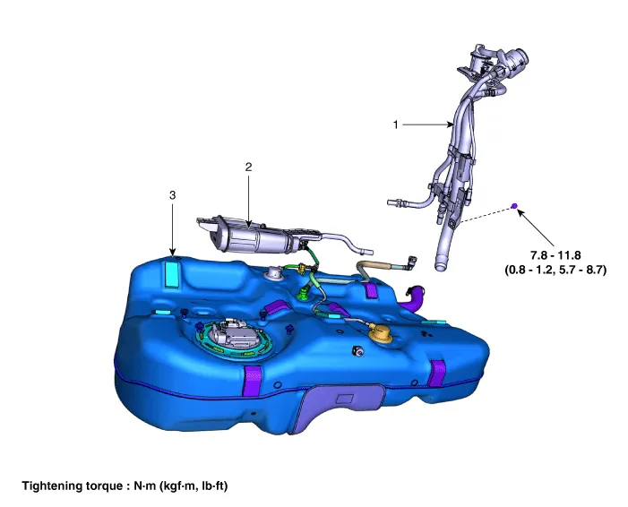
| 1. Filler-Neck Assembly 2. Canister |
3. Fuel Tank Complete |
Repair procedures
| Removal |
| 1. |
Disconnect the negative (-) battery terminal. |
| 2. |
Remove the rear wheel guard. (Refer to Body - "Rear Wheel Guard") |
| 3. |
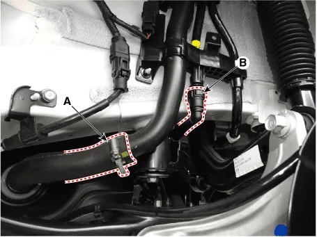
Disconnect the fuel filler hose (A) and leveling quick-connector (B).
|
| 4. |
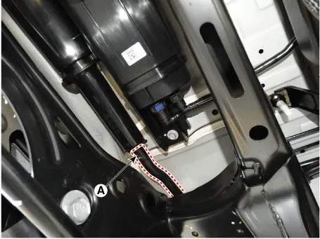
Disconnect the ventilation hose (A).
|
| 5. |
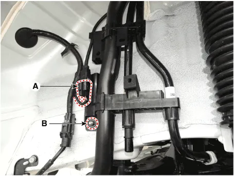
Remove the filler-neck assembly by loosening the mounting nut (B) after disconnecting the canister close valve connector (A).
|
| Installation |
| 1. |
Install in the reverse order of removal. |
Components and components location Component 1. Filler-Neck Assembly 2. Fuel Tank Complete 3. Fuel Line Repair procedures Removal 1.
Components and components location Components 1. Clip 2. Delivery Pipe 3. Injector Repair procedures Removal 1.
Other information:
Kia Optima DL3 2019-2026 Service and Repair Manual: Power Door Lock Switch
Repair procedures Inspection Power Window Main Switch Diagnosis With KDS 1. In the body electrical system, failure can be quickly diagnosed by using the vehicle diagnostic system (KDS). The diagnostic system (KDS) provides the following information.
Kia Optima DL3 2019-2026 Service and Repair Manual: Power Door Mirror Actuator
Schematic diagrams Connector and Terminal Function Repair procedures Inspection 1. Disconnect the negative battery terminal. 2. Remove the front door trim. (Refer to Body - "Front Door Trim") 3.
Categories
- Manuals Home
- Kia Optima Owners Manual
- Kia Optima Service Manual
- Battery
- Body Electrical System
- Cooling System
- New on site
- Most important about car
