Kia Optima DL3: Power Train / Automatic Transaxle Fluid
Repair procedures
| Inspection |
Automatic Transaxle Fluid (ATF) Level Check
When checking the ATF level, be careful not to allow foreign substance (like dust) to enter through the filler hole. |

| 1. |
Remove the air cleaner assembly. G 2.0 MPI (Refer to Engine Mechanical System - "Air Cleaner") G 2.5 GDI (Refer to Engine Mechanical System - "Air Cleaner") |
| 2. |
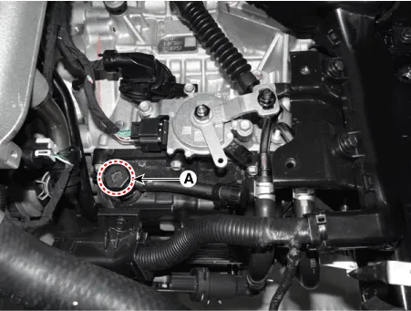
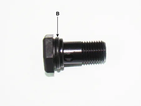
Add 0.7 L of ATF SP-IV through the ATF filler hole after removing the eyebolt (A). [G 2.0 MPI - A6MF1-2]
[G 2.5 GDI - A8MF1]
|

| 3. |
Remove the inhibitor switch. [G 2.0 MPI - A6MF1-2 Only] (Refer to Automatic Transaxle Control System - "Inhibitor Switch") |
| 4. |
Start the engine to warm up the ATF.
|
| 5. |
Check by using KDS that the temperature of the ATF is between 50°C and 60°C (122-140°F). |
| 6. |
Move the shift lever slowly from "P" to "D", then back to "P". Repeat this sequence two times and then move the shift lever to "P" range.
|
| 7. |
Remove the under cover. G 2.0 MPI (Refer to Engine Mechanical System - "Engine Room Under Cover") G 2.5 GDI (Refer to Engine Mechanical System - "Engine Room Under Cover") |
| 8. |
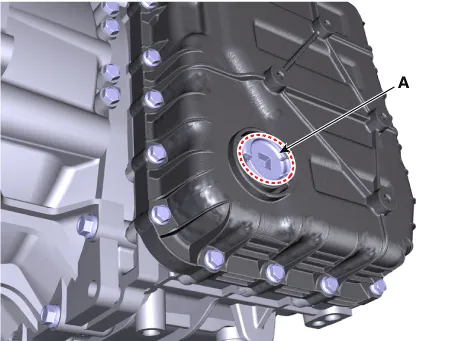
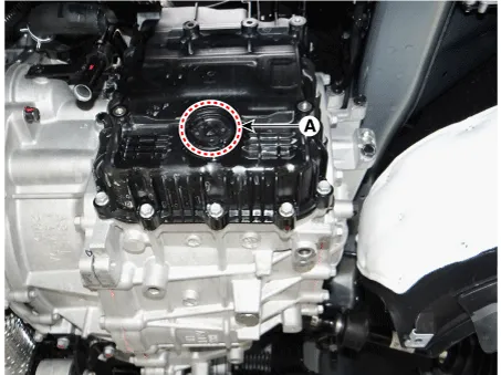
Lift the vehicle and remove the ATF level plug (A) from the valve body cover.
[G 2.0 MPI - A6MF1-2]
[G 2.5 GDI - A8MF1]
|
| 9. |
Check the ATF level.
|
| 10. |
Install the ATF level plug (A).
[G 2.0 MPI - A6MF1-2]
[G 2.5 GDI - A8MF1]
|
| 11. |
Lower the vehicle and install the eyebolt (A).
[G 2.0 MPI - A6MF1-2]
[G 2.5 GDI - A8MF1]
|
| 12. |
Install the inhibitor switch. [G 2.0 MPI - A6MF1-2 Only] (Refer to Automatic Transaxle Control System - "Inhibitor Switch") |
| 13. |
Install the air cleaner assembly. G 2.0 MPI (Refer to Engine Mechanical System - "Air Cleaner") G 2.5 GDI (Refer to Engine Mechanical System - "Air Cleaner") |
| 14. |
Install the under cover. G 2.0 MPI (Refer to Engine Mechanical System - "Engine Room Under Cover") G 2.5 GDI (Refer to Engine Mechanical System - "Engine Room Under Cover") |
Repair procedures Inspection [On vehicle inspection] 1. Accelerate the engine to about 3,000 rpm 3 times or more.
Repair procedures Inspection Vapor hose 1. Check all the clamps for tightness and the connections for leakage. 2.
Other information:
Kia Optima DL3 2019-2026 Service and Repair Manual: Power Seat Motor
Components and components location Components 1. Lumbar support motor 2. Reclining motor 3. Front height motor 4. Rear height motor 5. Slide motor Repair procedures Inspection 1.
Kia Optima DL3 2019-2026 Service and Repair Manual: Smart Key System
Specifications Specifications Smart Key Unit Items Specification Rated voltage DC 12 V Operation voltage DC 9 - 16 V Operation temperature -40 to 185°F (-40 to 85°C) RF Receiver Items
Categories
- Manuals Home
- Kia Optima Owners Manual
- Kia Optima Service Manual
- Body (Interior and Exterior)
- Cooling System
- Engine Mechanical System
- New on site
- Most important about car
