Kia Optima DL3: Smart Key System / Smart Key Unit
Schematic diagrams
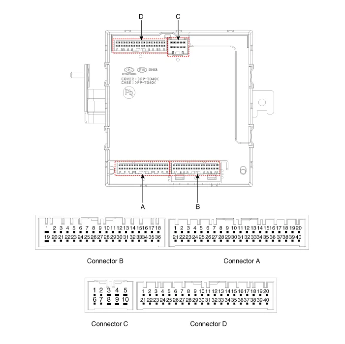
| Connector and Terminal Function |
|
Pin |
Function |
|||
|
Connector A |
Connector B |
Connector C |
Connector D |
|
|
1 |
- |
Front washer switch (Output) |
- |
Driver outside handle switch (Input) |
|
2 |
Rear seat belt indicator_Left (Output) |
- |
ESCL Enable (Output) |
Assist outside handle switch (Input) |
|
3 |
- |
- |
ESCL - (Output) |
- |
|
4 |
- |
- |
- |
- |
|
5 |
External buzzer (Output) |
- |
- |
RPM (Input) |
|
6 |
Rear seat belt indicator_Center (Output) |
Wiper parking switch (Input) |
- |
SSB symbol illumination (+) (Output) |
|
7 |
Puddle pocket lamp (Output) |
- |
ESCL Unlock switch (Input) |
ACC relay (Output) |
|
8 |
Rear seat belt indicator_Right (Output) |
Brake switch (Input) |
- |
IGN1 relay (Output) |
|
9 |
- |
- |
- |
IGN2 relay (Output) |
|
10 |
Headlamp high switch (Input) |
Front wiper volume switch (Input) |
ESCL + (Output) |
Starter relay (Output) |
|
11 |
- |
- |
|
Assist outside handle antenna (+) (Output) |
|
12 |
- |
LIN4 (Safety ECU) |
Interior antenna 2 (+) (Output) |
|
|
13 |
Rear view switch (Input) |
PAS Option (Input) |
Trunk interior antenna 3 (+) (Output) |
|
|
14 |
- |
- |
Interior antenna 1 (+) (Output) |
|
|
15 |
RPAS Power (Output) |
B-CAN (Low) |
Bumper antenna (+) (Output) |
|
|
16 |
FRAS Power (Output) |
B-CAN (High) |
Driver outside handle antenna (+) (Output) |
|
|
17 |
PAS/RPAS Power (Input) |
- |
- |
|
|
18 |
- |
Ground (Power) |
- |
|
|
19 |
- |
- |
- |
|
|
20 |
Ground (ECU) |
Immobilizer power (Output) |
- |
|
|
21 |
- |
Immobilizer ground (Output) |
SSB switch 1 (Input) |
|
|
22 |
K-Line_Immobilizer |
- |
SSB switch 2 (Input) |
|
|
23 |
- |
PAS/RPAS Switch indicator (Output) |
Clutch IGN lock switch |
|
|
24 |
- |
Front wiper switch (Input) |
ESCL COM |
|
|
25 |
Sunroof status (Input) |
- |
Wheel speed sensor (Input) |
|
|
26 |
PAS/RPAS Switch (Input) |
Multifunction switch ground (Input) |
- |
|
|
27 |
ATM Solenoid (Output) |
Wiper power relay (Output) |
- |
|
|
28 |
LIN3 (Rain sensor) |
Auto light sensor ground (Output) |
- |
|
|
29 |
LIN2 (ROA) |
Auto light sensor signal (Input) |
- |
|
|
30 |
LIN1 (PDW-F or PDW-R) |
Auto light sensor power (Output) |
Start feed back (Input) |
|
|
31 |
Door unlock signal (For IFU) EMS (Output) |
- |
Assist outside handle antenna (-) (Output) |
|
|
32 |
Light switch (Input) |
Front wiper high relay (Output) |
Interior antenna 2 (-) (Output) |
|
|
33 |
Fog switch (Input) |
Front wiper low relay (Output) |
Trunk interior antenna 3 (-) (Output) |
|
|
34 |
IGN2 (Input) |
Front wiper low backup switch (Input) |
Interior antenna 1 (-) (Output) |
|
|
35 |
IGN1 (Input) |
P-CAN (Low) |
Bumper antenna (-) (Output) |
|
|
36 |
ACC (Input) |
P-CAN (High) |
Driver outside handle antenna (-) (Output) |
|
|
37 |
Battery + (ECU) |
|
- |
|
|
38 |
Battery + (Power) |
- |
||
|
39 |
- |
- |
||
|
40 |
Front heated nozzle (Output) |
'P' Position (input) |
||
Repair procedures
| Removal |
Integrated Body control Unit (IBU)
| 1. |
Remove the IBU. (Refer to Body Electrical System - "Integrated Body Control Unit") |
Door Outside Handle
| 1. |
Remove the front door outside handle. (Refer to Body - "Front Door Outside Handle") |
Trunk Open Switch
| 1. |
Remove the center rear combination lamp. (Refer to Lighting System - "Rear Combination Lamp") |
| 2. |
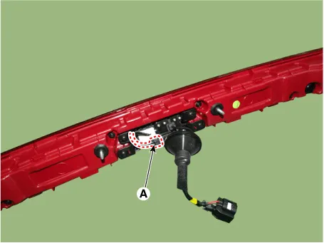
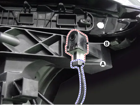
Disconnect the trunk open switch connector (A).
|
| 3. |
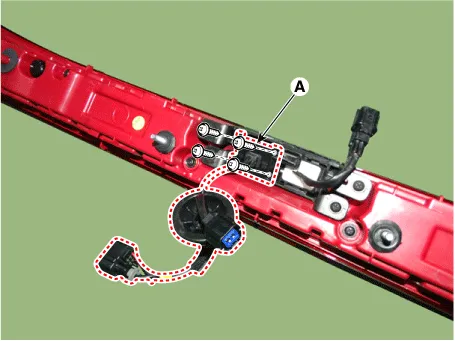
Remove the rear view camera (A) by loosening the mounting screws.
|
| 4. |
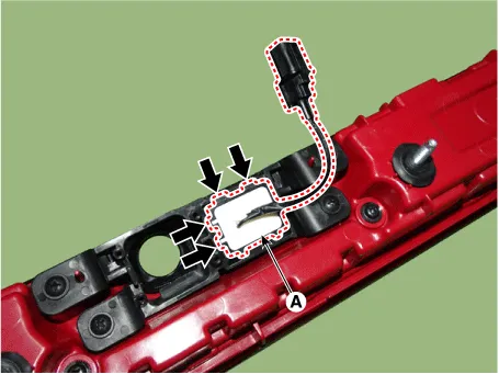
Remove the trunk open switch (A) by pressing the hooks.
|
Buzzer
| 1. |
Disconnect the negative battery terminal. |
| 2. |
Remove the front bumper assembly. (Refer to Body - "Front Bumper assembly") |
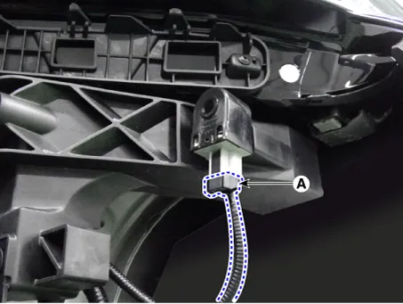
| 3. |
Remove the buzzer (B) after disconnecting the connector (A).
|
| Installation |
| 1. |
Install in the reverse order of removal. |
| Inspection |
Integrated Body control Unit (IBU)
| 1. |
Inspect the IBU by using the KDS. (Refer to Smart Key System - "Smart Key Diagnostic") |
Door Outside Handle
| 1. |
Remove the front door outside handle. (Refer to Body - "Front Door Outside Handle") |
| 2. |
Disconnect the front door outside handle connector and then check for continuity between terminals No 3 and No 6.
|
Trunk Open Switch
| 1. |
Disconnect the negative battery terminal. |
| 2. |
Remove the trunk lid trim. (Refer to Body - "Trunk Lid Trim") |
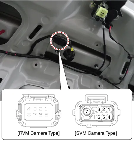
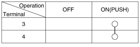
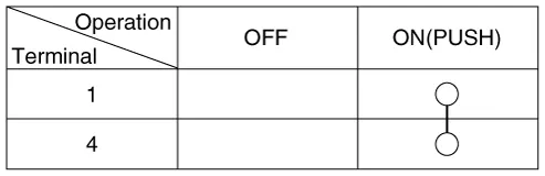
| 3. |
Check for continuity between the terminals.
[RVM Camera Type]
[SVM Camera Type]
|
Buzzer
| 1. |
Disconnect the negative battery terminal. |
| 2. |
Remove the front bumper assembly. (Refer to Body - "Front Bumper assembly") |
| 3. |
Disconnect the buzzer connector (A). |
| 4. |
Test the buzzer by connecting battery power to the terminal 2 and ground the terminal 1.
|
Repair procedures Adjustment Smart Key Code Saving 1. Connect the VCI II in driver side crash pad lower panel, turn the power on KDS.
Repair procedures Removal Interior Antenna 1 1. Disconnect the negative battery terminal. 2. Remove the surround view monitor (SVM) unit.
Other information:
Kia Optima DL3 2019-2026 Service and Repair Manual: Panorama Sunroof Switch
Schematic diagrams Connector and Terminal Function Repair procedures Inspection 1. Remove the overhead console lamp. (Refer to Lighting System - "Overhead Console Lamp") 2. Check for continuity between the terminals in each switch position according to the table
Kia Optima DL3 2019-2026 Service and Repair Manual: Power Seat Motor
Components and components location Components 1. Lumbar support motor 2. Reclining motor 3. Front height motor 4. Rear height motor 5. Slide motor Repair procedures Inspection 1.
Categories
- Manuals Home
- Kia Optima Owners Manual
- Kia Optima Service Manual
- Floor Console Assembly
- Timing Chain
- External Amp
- New on site
- Most important about car
