Kia Optima DL3: Body (Interior and Exterior) / Panorama Sunroof
Components and components location
| Component |
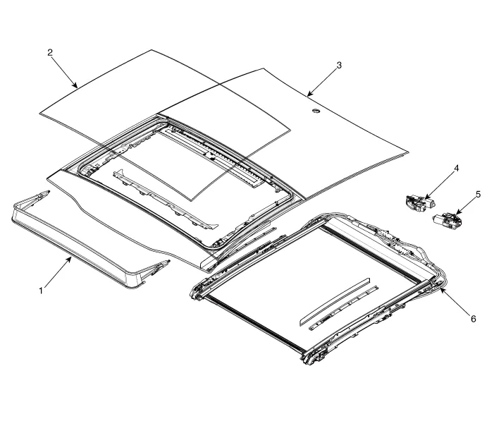
| 1. Panorama sunroof deflector
2. Movable glass 3. Rear glass |
4. Glass motor assembly 5. Roller blind motor assembly 6. Mechanism rail assembly |
Repair procedures
| Alignment |
Glass step alignment
| 1. |
Perform considerable step alignment after replacing movable glass (A).
|

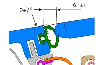


| 2. |
Perform hight adjustment releasing height adjust screw (A) a bit.
|

Initializing motor
| 1. |
Perform rest procedure When Start [ON] or motor is running. |
| 2. |
Close enough panorama sunroof glass (about 5 sec) and blind (about 5 sec). |
| 3. |
Hand off from adjusting lever when glass and blind are closed enough. |
| 4. |
Press adjusting lever (10 sec) until glass and blind is moving a bit once again to sunroof close direction when glass and blind is closed enough. |
| 5. |
Hand off and press panorama sunroof adjusting lever to close direction then glass and blind is opened and closed [①Blind is open in slide mode ②Sunroof glass is opened and closed in slide mode after tilt ③Blind is closed] Initializing is done. Never hand off from adjusting lever until finished completely. |
In case of motor initializing
| 1. |
First operation after manufactured |
| 2. |
When rest value is initialized or damaged by power failure or discharging |
| 3. |
After operating emergency handle |
| 4. |
When replacing battery and fuse |
| 5. |
After replacing motor and reparing sunroof |
Emergency operation
| 1. |
Emergency operation of panorama sunroof should not be performed except in case of closing or opening panorama sunroof when motor is defected. |
| 2. |
Panorama sunroof should be closed or opened after removing roof trim using hexgonal wrench. Do not use excessive force. |
| 3. |
Perform initialization when necessary according the initialization procedure. [Movable glass motor (A) Roller blind motor (B)]
|

- Movable Glass
- Front Glass
- Rear Glass
- Panorama Sunroof Deflector
- Mechanism Rail
- Roller Blind
- Panorama Sunroof Assembly
- Roll Blind Cable Assembly
Repair procedures Replacement Put on gloves to protect your hands. • Use a plastic panel removal tool to remove interior trim pieces without marring the surface.
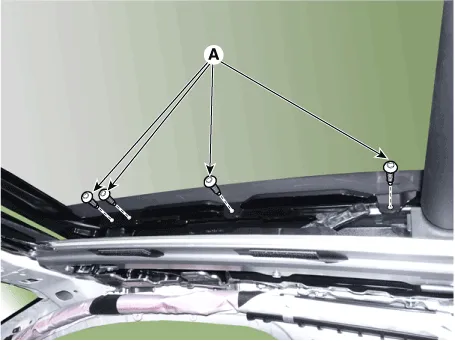
Repair procedures Replacement 1. Open movable glass completely pressing panorama sunroof switch. 2. Remove the slide folding cover (A).
Other information:
Kia Optima DL3 2019-2026 Service and Repair Manual: Keyless Entry And Burglar Alarm
Specifications Specification Item Specification Operating temperature 14 - 140°F (-10 - 60°C) RF Modulation FSK RF Frequency 433.
Kia Optima DL3 2019-2026 Service and Repair Manual: Heater Unit
Components and components location Component Location 1. Heater unit assembly Compoents 1. Mode control actuator 2. Temperature control actuator [LH] 3. PTC Heater dummy 4.
Categories
- Manuals Home
- Kia Optima Owners Manual
- Kia Optima Service Manual
- Cooling System
- Steering System
- Motor Driven Power Steering
- New on site
- Most important about car
