Kia Optima DL3: Automatic Transaxle System
Service data
| Service data |
Automatic Transaxle
|
Item |
Specification |
|
|
Transaxle model |
A6MF1-2 |
|
|
Engine model |
G 2.0 MPI (Gasoline) |
|
|
Torque converter type |
3-element, 1-stage, 2-phase type |
|
|
Oil pump type |
Megafloid |
|
|
Component element |
Oil filter |
1 unit |
|
Clutch |
2 units |
|
|
One-way clutch |
1 unit |
|
|
Brake |
3 units |
|
|
Planetary gear |
3 units |
|
|
Fluid pressure balance piston |
2 units |
|
|
Accumulator |
4 units |
|
|
Solenoid valve |
7 units (*VFS: 6, ON/OFF: 1) |
|
*VFS: Variable Force Solenoid
Inhibitor Switch
|
Item |
Specification |
|
|
Power supply (V) |
4.5 - 5.5 V |
|
|
Output type |
Shifting range (P/R/N/D) |
Non-contact (2 channel PWM signal) |
|
Start, Back-up lamp |
Contact |
|
Sensor
|
Item |
Specification |
|
|
Oil temperature sensor |
Type |
*NTC thermistor |
|
Temp.[(°C)°F] / Resistance (kΩ) |
(-40)-40 / 48.1 |
|
|
(-20)-4.0 / 15.6 |
||
|
(0)32.0 / 5.88 |
||
|
(20)68.0 / 2.51 |
||
|
(40)104.0 / 1.19 |
||
|
(60)140.0 / 0.61 |
||
|
(80)176.0 / 0.32 |
||
|
(100)212.0 / 0.18 |
||
|
(120)248.0 / 0.10 |
||
|
(140)284.0 / 0.06 |
||
|
(150)302.0 / 0.05 |
||
|
Input speed sensor |
Type |
Hall effect sensor |
|
Operating condition (°C)°F |
(-40 to 150)-40 to 302 |
|
|
Output voltage (V) |
High: 1.18 - 1.68 |
|
|
Low: 0.59 - 0.84 |
||
|
Output speed sensor |
Type |
Hall effect sensor |
|
Operating condition (°C)°F |
(-40 to 150)-40 to 302 |
|
|
Output voltage (V) |
High: 1.18 - 1.68 |
|
|
Low: 0.59 - 0.84 |
||
*NTC: Negative Temperature Coefficient
Solenoid Valve
|
Item |
Specification |
|
|
*T/CON_VFS |
Control type |
N/L (Normal Low) |
|
Control pressure kPa (kgf/cm², psi) |
0 - 519.75 (0 - 5.3, 0 - 75.38) |
|
|
Current (mA) |
0 - 850 |
|
|
Coil resistance (Ω) |
5.1 ± 0.3 |
|
|
*35R/C_VFS |
Control type |
N/L (Normal Low) |
|
Control pressure (kPa (kgf/cm², psi)) |
0 - 1,569.06 (0 - 16, 0 - 227.57) |
|
|
Current (mA) |
0 - 1,100 |
|
|
Coil resistance (Ω) |
5.3 ± 0.3 |
|
|
*26/B_VFS |
Control type |
N/L (Normal Low) |
|
Control pressure (kPa (kgf/cm², psi)) |
0 - 1,569.06 (0 - 16, 0 - 227.57) |
|
|
Current (mA) |
0 - 1,100 |
|
|
Coil resistance (Ω) |
5.3 ± 0.3 |
|
|
*UD/B_VFS |
Control type |
N/H (Normal High) |
|
Control pressure kPa (kgf/cm², psi) |
0 - 1,569.06 (0 - 16, 0 - 227.57) |
|
|
Current (mA) |
0 - 1,100 |
|
|
Coil resistance (Ω) |
5.3 ± 0.3 |
|
|
*OD/C_VFS |
Control type |
N/H (Normal High) |
|
Control pressure kPa (kgf/cm², psi) |
0 - 1,569.06 (0 - 16, 0 - 227.57) |
|
|
Current (mA) |
0 - 1,100 |
|
|
Coil resistance (Ω) |
5.3 ± 0.3 |
|
|
*Line_VFS |
Control type |
N/H (Normal High) |
|
Control pressure kPa (kgf/cm², psi) |
0 - 519.75 (0 - 5.3, 0 - 75.38) |
|
|
Current (mA) |
0 - 850 |
|
|
Coil resistance (Ω) |
5.1 ± 0.3 |
|
|
*SS-A_ON/OFF |
Control type |
ON/OFF |
|
Voltage (V) |
9 - 16 |
|
|
Control pressure kPa (kgf/cm², psi) |
0 - 490.33 (0 - 5.0, 0 - 71.12) |
|
|
Coil resistance (Ω) |
10.0 - 11.0 |
|
*T/CON_VFS: Torque converter control solenoid valve
*35R/C_VFS: 35R clutch control solenoid valve
*26/B_VFS: 26 Brake control solenoid valve
*UD/B_VFS: Underdrive brake control solenoid valve
*OD/C_VFS: Overdrive clutch control solenoid valve
*LINE_VFS: Line pressure control solenoid valve
*SS-A_ON/OFF: Shift control solenoid valve-A
Solenoid Valve Operation Table
|
|
UD |
OD & LR |
35 R |
26 |
SS - A |
|
P |
● |
|
|
|
● |
|
N |
● |
|
|
|
● |
|
1 st |
|
Δ |
|
|
Δ |
|
2 nd |
|
● |
|
● |
|
|
3 rd |
|
● |
● |
|
|
|
4 th |
|
|
|
|
|
|
5 th |
● |
|
● |
|
|
|
6 th |
● |
|
|
● |
|
|
REV |
● |
|
● |
|
● |
● : Connection status
Δ : Connected with vehicle speed above 8km/h (5mph)
Clutch & Brake Operation Table
|
|
Clutch |
Brake |
||||
|
OD/C |
35R/C |
OWC |
LR/B |
UD/B |
26/B |
|
|
N, P |
|
|
|
● |
|
|
|
1 |
|
|
● |
Δ |
● |
|
|
2 |
|
|
|
|
● |
● |
|
3 |
|
● |
|
|
● |
|
|
4 |
● |
|
|
|
● |
|
|
5 |
● |
● |
|
|
|
|
|
6 |
● |
|
|
|
|
● |
|
R |
|
● |
|
● |
|
|
● : Operation status
Δ : Connected with vehicle speed above 8km/h (5mph)
Tightening torque
| Tightening Torque |
|
Item |
N·m
|
kgf·m |
lb·ft
|
|
TCM mounting nut & bolt |
9.8 - 11.8 |
1.0 - 1.2 |
7.2 - 8.7 |
|
Shift cable bracket mounting bolt |
14.7 - 21.6 |
1.5 - 2.2 |
10.9 - 15.9 |
|
Shift cable retainer mounting nut |
9.8 - 14.7 |
1.0 - 1.5 |
7.2 - 10.9 |
|
Shift cable mounting nut |
9.8 - 14.7 |
1.0 - 1.5 |
7.2 - 10.9 |
|
Shift lever assembly mounting bolt |
8.8 - 13.7 |
0.9 - 1.4 |
6.5 - 10.1 |
|
Input shaft speed sensor mounting bolt |
9.8 - 11.8 |
1.0 - 1.2 |
7.2 - 8.7 |
|
Output shaft speed sensor mounting bolt |
9.8 - 11.8 |
1.0 - 1.2 |
7.2 - 8.7 |
|
Inhibitor switch mounting bolt |
9.8 - 11.8 |
1.0 - 1.2 |
7.2 - 8.7 |
|
Manual control lever mounting bolt |
17.7 - 24.5 |
1.8 - 2.5 |
13.0 - 18.1 |
|
Valve body cover mounting bolt |
11.8 - 13.7 |
1.2 - 1.4 |
8.7 - 10.1 |
|
Fluid drain plug |
33.3 - 43.1 |
3.4 - 4.4 |
24.6 - 31.8 |
|
Torque converter mounting bolt |
45.1 - 52.0 |
4.6 - 5.3 |
33.3 - 38.3 |
|
Starter mounting bolt |
49.0 - 63.7 |
5.0 - 6.5 |
36.2 - 47.0 |
|
Automatic transaxle upper mounting bolt (TM=>Eng) |
42.2 - 53.9 |
4.3 - 5.5 |
31.1 - 39.8 |
|
Automatic transaxle lower mounting bolt (Eng=>TM) |
42.2 - 48.1 |
4.3 - 4.9 |
31.1 - 35.4 |
|
42.2 - 53.9 |
4.3 - 5.5 |
31.1 - 39.8 |
|
|
Automatic transaxle support bracket mounting bolt |
58.9 - 78.5 |
6.0 - 8.0 |
43.4 - 57.8 |
|
Automatic transaxle mounting bracket bolt |
107.9 - 127.5 |
11.0 - 13.0 |
79.6 - 94.0 |
|
Roll rod bracket mounting bolt |
49.0
- 63.7 |
5.0 - 6.5 |
36.2 - 47.0 |
|
107.9 - 127.5 |
11.0 - 13.0 |
79.6 - 94.0 |
|
|
Roll rod support bracket mounting bolt |
49.0 - 68.6 |
5.0 - 7.0 |
36.2 - 50.6 |
|
Torque converter housing mounting bolt |
27.5 - 34.3 |
2.8 - 3.5 |
20.3 - 25.3 |
|
Oil filter mounting bolt |
9.8 - 11.8 |
1.0 - 1.2 |
7.2 - 8.7 |
|
Oil pump mounting bolt |
19.6 - 25.5 |
2.0 - 2.6 |
14.5 - 18.8 |
Lubricant
| Lubricants |
|
Item |
Capacity |
Recommended |
||||
|
ATF (Automatic Transaxle Fluid) |
6.7 L (1.77 U.S gal., 7.08 U.S.qt., 5.90 Imp.qt.) |
|
Special service tools
| Special Service Tools |
|
Tool Name / Number |
Illustration |
Description |
|
Engine support fixture (bar) 09200-3N000 |
|
Used for holding engine assembly when removing / installing transaxle
※ Refer to the engine support fixture assembly drawing below. |
|
Engine support fixture (Rear supporter) 09200-L1100 |
|
Used for holding engine assembly when removing / installing transaxle
※ Refer to the engine support fixture assembly drawing below. |
|
Engine support fixture (Front supporter) 09200-L1200 |
|
Used for holding engine assembly when removing / installing transaxle
※ Refer to the engine support fixture assembly drawing below. |
|
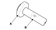
Oil seal installer A : 09452-26100 (Installer) B : 09231-H1100 (Handle) |
|
Used for installing differential oil seal |
|
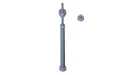
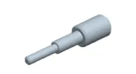
Inhibitor switch guide pin 09480-A3800 |
|
Used for fixing "N" range when installing inhibitor switch |
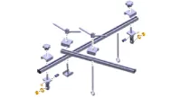

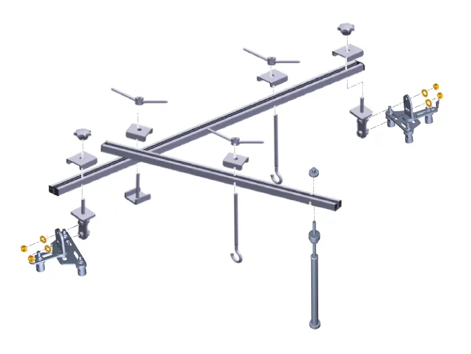
Engine support fixture assembly drawing
Troubleshooting
| Troubleshooting |
| Limp Home Mode |
Features a fail-safe function that prevents dangerous situations in the event of a transaxle failure. The vehicle will be driven in limp home mode if the transaxle malfunctions. In this mode, the transaxle operates at a minimal functionality level (fixed shifting, limited shifting, reverse, neutral), making it possible for the vehicle to reach a service center.
Limp Home Mode : Limited shifting Mechanical limp home mode : Fixed shifting (failure of mechanical parts, solenoid valves, TCM, CAN communication) |

Troubleshooting
|
Trouble symptom |
Suspected area |
Remedy |
|
Shifting delay, Shifting shock, Poor acceleration |
Damaged clutch / brake |
Replace the brake or clutch. |
|
Faulty hydraulic control |
Inspect the solenoid valve. |
|
|
Faulty hydraulic supply |
Inspect the fluid level. |
|
|
Inspect the fluid cleanliness |
||
|
Replace the oil pump. |
||
|
TCM learning not performed |
Perform the TCM adaptive value learning. |
|
|
Mechanical limp home mode (locked into 4th, manual shifting disabled) |
Faulty Solenoid valve |
Inspect the solenoid valve. |
|
Replace the valve body. |
||
|
Faulty TCM |
Replace the TCM. |
|
|
Faulty CAN communication |
Inspect the CAN communication line. |
|
|
Limp home mode (locked into 4th, manual shifting 2nd-4th enabled) |
Faulty input & output speed sensor |
Replace the input & output speed sensor. |
|
Limp home mode (1st-3rd shifting disabled, 4th-6th shifting enabled) |
Faulty inhibitor switch |
Replace the inhibitor switch. |
|
Manual shifting disabled |
Faulty TCM |
Replace the TCM. |
|
Faulty connector connection |
Check the connection of manual mode connector. |
|
|
Faulty manual mode switch |
Replace the manual mode switch housing. |
- Automatic Transaxle Control System
- Transaxle Control Module (TCM)
- Transaxle Oil Temperature Sensor (Main Harness)
- Speed Sensor
- Inhibitor Switch
- Shift Lever
- Shift Cable
- Automatic Transaxle System
- Hydraulic System
- Fluid
- Valve Body
- Oil Pump
- Torque Converter Control Solenoid Valve (T/CON_VFS)
- 35R Clutch Control Solenoid Valve (35R/C_VFS)
- 26 Brake Control Solenoid Valve (26/B_VFS)
- Underdrive Brake Control Solenoid Valve (UD/B_VFS)
- Overdrive Clutch Control Solenoid Valve (OD/C_VFS)
- Line Pressure Control Solenoid Valve
- SS-A Solenoid Valve (ON/OFF)
Specifications Specification Item Specification Coil Resistance (Ω) 14.5 [20°C(68°F)] Description and operation Description • Based on information from various sensors, the ECM can calculate the fuel amount to be injected.
Description and operation Description Automatic transaxle control system relies on various measurements to determine the current control status and determine the necessary compensation values.
Other information:
Kia Optima DL3 2019-2026 Service and Repair Manual: Vanity Lamp
Repair procedures Removal When removing with a flat-tip screwdriver or remover, wrap protective tape around the tools to prevent damage to components. 1.
Kia Optima DL3 2019-2026 Service and Repair Manual: Heater Control Unit
Components and components location Components Connector Pin Function [Connector A] Pin NO Funtion Pin NO Funtion 1 Ground 11 Ground 2 Clean signal 12 -
Categories
- Manuals Home
- Kia Optima Owners Manual
- Kia Optima Service Manual
- Front Axle Assembly
- Engine Control Module (ECM)
- Headlamps
- New on site
- Most important about car
